Download

1 / 29
390 likes | 1.46k Views
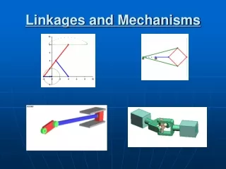
Linkages. FUNDAMENTALS Topic 4 Gerald Rothenhofer 9/21/2009. What is a Linkage?.

E N D
Linkages FUNDAMENTALS Topic 4 Gerald Rothenhofer 9/21/2009
What is a Linkage? • A mechanical linkage is a series of rigid links connected with joints to form a closed chain, or a series of closed chains. Each link has two or more joints, and the joints have various degrees of freedom to allow motion between the links. A linkage is called a mechanism if two or more links are movable with respect to a fixed link. Mechanical linkages are usually designed to take an input and produce a different output, altering the motion, velocity, acceleration, and applying mechanical advantage. • A linkage designed to be stationary is called a structure.en.wikipedia.org/wiki/Linkage_(mechanical)
History • Leonardo da Vinci (1452, 1519), Codex Madrid I. • Industrial Revolution was the boom age of linkages: cloth making, power conversion, speed regulation, mechanical computation, typewriting and machining
Linkages Today • In many applications (typewriting) linkages have been replaced by electronics. • Still linkages can have a cost advantage over electronic solutions: Couple different outputs by a mechanism rather than using one motor per output and electronics to achieve the coupling. • Current applications: Sports Equipment, Automotive (HVAC modules), Precision Machinery (Compliant Mechanisms), Medical Devices
Linkage Categorization • Planar Linkages • Three bar • Four bar • Slider Crank • Five bar • Six bar • …be creative… • Spatial Linkages
Degrees of Freedom • Planar Linkages: • F=3*(N-1)-2*J1-Jh • F – total degrees of freedom • N – number of links • J1 – constraints by 1DOF joints • Jh – constraints by 2DOF joints
Four Bar • Grashof: The sum of the shortest (S) and longest (L) links of a planar four-bar linkage must be smaller than the sum of the remaining two links (P, Q). In this case the shortest link can rotate 360degree relative to the longest link. • L + S < P + Q: crank-rocker, double-crank, rocker-crank, double-rocker • L + S = P + Q: crank-rocker, double-crank, rocker-crank, double-rocker, note: linkage can change its closure in singularity positions (all links aligned) • If L + S > P + Q, double-rocker, no continuous rotation of any link
C γ D B A Transmission Angles – Four Bar • A – ground link • B – input link • C – coupler • D – output link • Angle between coupler and output link should be 40º≤γ≤140º Zero torque at output link if γ=0º or γ=180º
Especially important in critical position such as within the main working range or high load positions Minimize α Minimize |θ2-90°| No stick condition: 1/tan(α)<μ y Θ2 b a α T x Θ1 Transmission Angles – Slider Crank
C D B A Four Bar Synthesis • A – ground link • B – input link • C – coupler • D – output link • Function Generation (input/output relation) • Line Path Generation (line on coupler) • Point Path Generation (coupler point)
Cognate Mechanisms • Provide identical motion of a point or link • Here: coupler point cognate
Four Bar Function Generation • Two angular displacements • Only one initial position; either primary or secondary side can be chosen freely (here 60°) • E.g.: • Primary side moves by 2x 20 ° • Secondary side moves by 35°+30°
Crank Rocker Design • Design in extreme positions • Typically design for crank movement >180º depending on required transmission ratio i.e. rocker should move slowly when load is heavy, the return fast • In this example rocker moves through 60º while the crank moves through 180º+10º=190º
Slider Crank Synthesis I • Two point synthesis
Slider Crank Synthesis II • Three point synthesis by geometrical inversion
Other Basic Four Bar Design Methods • Approximate function generation • Approximate coupler point path generation • Uncorrelated with input • Correlated with input • Slider crank synthesis by approximation
What is possible with advanced design methods? • Four coupler position synthesis • In some cases five coupler position synthesis is achievable • Straight line motion • Complex linkages (more than four bars) • Spatial linkages
Five Bar • How many degrees of freedom? • Why does it work?
Six Bar • Watt & Stephenson Linkages • approximate dwells or better MTB suspension
b ψ ey rp c a ex Θ1 d Θ2 Four Bar Analysis I • Θ2 is a complicated trigonometric function of Θ1, Θ2=f(Θ1)
θ2 b a F, V R T1, ω1 y0 θ1 φ x0 Slider Crank Analysis • F is maximum available force (no friction or other loads taken into account)
θ2 b a F, V R T1, ω1 y0 θ1 φ x0 Slider Crank Transmission Ratio • The transmission ratio determines the relation of slider (flapper) position and motor angle.
Assumes that load forces are constant Average and max load forces should be used to check for safety factors δl arc length between starting point and end point of slider movement y b a δl δΘin Tin x Power Budget
y Θ2 b a α T x Θ1 F y Θ2 F b a α RF T x Θ1 Slider Friction I
y Θ2 a F α T x Θ1 F┴ F║ Slider Friction II