Download
1 / 21
210 likes | 338 Views
Learn how phasors express current-voltage relationships for inductors, capacitors, and resistors through complex exponentials. Explore examples and computations in a circuit element context.

E N D
Phasor Relationships for Circuit Elements (7.4) Prof. Phillips April 16, 2003 lecture 20
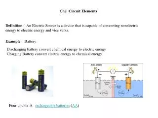
Phasor Relationships for Circuit Elements • Phasors allow us to express current-voltage relationships for inductors and capacitors much like we express the current-voltage relationship for a resistor. • A complex exponential is the mathematical tool needed to obtain this relationship. lecture 20
I-V Relationship for a Resistor Suppose that i(t) is a sinusoid: i(t) = IM ej(wt+q) Find v(t) + i(t) v(t) R – lecture 20
Computing the Voltage lecture 20
Class Example lecture 20
+ i(t) v(t) C – I-V Relationship for a Capacitor Suppose that v(t) is a sinusoid: v(t) = VM ej(wt+q) Find i(t) lecture 20
Computing the Current lecture 20
Phasor Relationship • Represent v(t) and i(t) as phasors: V = VMq I = jwCV • The derivative in the relationship between v(t) and i(t) becomes a multiplication by jw in the relationship between V and I. lecture 20
Example v(t) = 120V cos(377t + 30) C = 2mF • What is V? • What is I? • What is i(t)? lecture 20
Class Example lecture 20
I-V Relationship for an Inductor V = jwLI + i(t) v(t) L – lecture 20
Example i(t) = 1mA cos(2p 9.15•107t + 30) L = 1mH • What is I? • What is V? • What is v(t)? lecture 20
Class Example lecture 20
Circuit Element Phasor Relations(ELI and ICE man) lecture 20
Phasor Diagrams • A phasor diagram is just a graph of several phasors on the complex plane (using real and imaginary axes). • A phasor diagram helps to visualize the relationships between currents and voltages. lecture 20
An Example 2mA 40 + + VC 1mF – V w = 377 + 1kW VR – – lecture 20
An Example (cont.) I = 2mA 40 VR = 2V 40 VC = 5.31V -50 V = 5.67V -29.37 lecture 20
Phasor Diagram Imaginary Axis Real Axis V VC VR lecture 20
MATLAB Exercise • Let’s use MATLAB to plot an ac current and voltage, and then to graphically determine the lead-lag relationship • Start MATLAB on your computer • We begin by creating a time vector >> t = 0 : 0.0005 : 0.025; • Next, we create the voltage and current >> vt = 170 * cos(377*t+10*pi/180); >> it = 100 * cos(377*t-65*pi/180); lecture 20
MATLAB Exercise • Now we will graph v(t) and i(t) >> plot(t,vt,'b',t, it,'r--'); >> xlabel('Time (sec)'); >> ylabel('Voltage (Volts) or Current (Amps)'); >> title('Household AC Voltage-Current'); >> legend('v(t)=170cos(377t+10)', 'i(t)=100cos(377t-65)'); lecture 20
MATLAB Exercise • From the graphs created: • Determine whether the current leads the voltage, or vice versa • Determine the amount of lead by the current or voltage • Compare the voltage-current lead-lag relationship obtained by graphical means above to an analytic solution which you should be able to compute lecture 20