Download
1 / 29
290 likes | 464 Views
PANAREA IMAT F. Aliotta IPCF-CNR, Messina, ITALY. ISIS is actually the world’s leading pulsed neutron and muon source. It is a high flux pulsed source (~10 12 n∙cm -2 ·s -1 ).

E N D
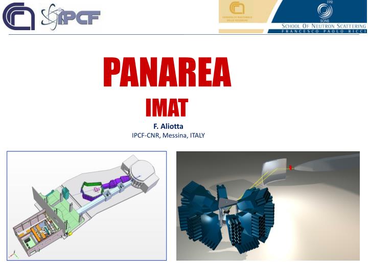
PANAREA IMAT F. Aliotta IPCF-CNR, Messina, ITALY
ISIS is actually the world’s leading pulsed neutron and muon source. It is a high flux pulsed source (~1012 n∙cm-2·s-1). The time width of the moderated neutron pulse at the beginning of its path toward the sample is ~20 ms and the pulse repetition rate is 60Hz. The time width of the pulse on the sample depends on the length of the path to the sample area (after tenths of meters the pulse width becomes several hundreds ms). With the project TS2, in July 2003 began the construction of a second target station at ISIS. On 3 August 2008, the first neutrons from the new target station have been measured. The ISIS second target station project was completed in 2009. All seven Phase One neutron instruments are operational. Since 1985, CNR has been supporting the access of italian researchers to the neutron spectroscopy techniques here available. CNR-CCLRC International Agreement for the utilization of the ISIS spallation neutron source in the Rutherford Appleton Laboratory. (CCLRC=Council for the Central Laboratory of the Research Council)
Diamond ISIS Harwell Science & Innovation Campus
Proton energy 800 MeV TS-I 20 instruments 50 Hz Target: W, clad in Ta 150 kW160 μA (240 μA) TS-II: 7 instruments 10 Hz Target: W, clad in Ta ( 6.6, 27 cm) 48 kW 40 μA (60 μA)
With the project TS2, in July 2003 began the construction of a second target station at ISIS. On 3 August 2008, the first neutrons from the new target station have been measured. The ISIS second target station project was completed in 2009. All seven Phase One neutron instruments are operational. In 2008 a new agreement for collaboration between CNR and STCF has been performed. Within this agreement a new project, PANAREA, will be developed, that will be co-financed by CNR and STCF (2008-2016). (STFC=Science and Technology Facilities Council) Since 1985, CNR has been supporting the access of italian researchers to the neutron spectroscopy techniques here available. CNR-CCLRC International Agreement for the utilization of the ISIS spallation neutron source in the Rutherford Appleton Laboratory. (CCLRC=Council for the Central Laboratory of the Research Council)
PANAREA CHIPIR CHIP IRradiation IMAT IMage and MATerials science and engineering Progetto per l'Applicazione dei Neutroni Alla Ricerca in Elettronica e Archeometria Agreement concerning collaboration in scientific research at the spallation neutron source ISIS [...] CNR shall collaborate with CCLRC in the exploitation of ISIS by making contributions as follows: [...] Aiming to collaborate with CCLRC in the development of mutually beneficial instrumentation and techniques associated with the utilisation of ISIS Target Station 1 and especially its new Target Station 2.
IMAT A thermal-cold imaging / materials science beamline for TS-II CHIPIR CHIP IRradiation IMAT IMage and MATerials science and engineering The possibility of non-destructive testing and the penetration power of neutrons is the basis of a materials science instrument for engineering, geology, and archaeological sciences. Imat will allow the study of novel alloys and composite materials, phase transformations, creeps and fatigue, corrosion, and ancient fabrication techniques. • Available Techniques: • Neutron radiography and tomography • Diffraction-enhanced imaging • Neutron strain scanning • Rapide texture analysis • Applications: • Aerospace and transportation • Fuel and fluid cell technology • Cultural heritage • Earth sciences • Engineerig and reverse engineering Imaging mode diffraction mode IMAT will be a world-leading pulsed-source cold neutron radiography station and facility for materials science, materials processing and engineering.
IMAT diffraction mode Texture analysis capabilitiesare already available at the GEM and POLARIS instruments on ISIS TS1. IMAT will have a highly flexible and spacious sample area to accommodate a diverse range of engineering-specific and user-supplied sample environment and processing cells and allow for motorised spatial scanning. IMAT will be significantly complementary to ENGIN-X (TS1) which is specifically designed for evaluating lattice spacings in engineering relevant materials in minimum times. IMAT will employ a relaxed resolution to bias towards higher intensity, and will provide greater solid angle detector coverage in order to evaluate texture, phase volume fractions, and strain orientation distributions in short data acquisition times. The simultaneous analysis of internal stress and texture will be a unique and key capability of the beamline. GEM POLARIS The instrument will be ideally suited to in-situ processing studies, in which materials are typically peak-broadened so that instrumental resolution is not a critical parameter.
The fine selection of the neutron energy allows to evidenciate any small local deformation of the crystaline lattice. Bragg edge analysis allows to obtain information about the stress and deformation distribution in mechanical components. Energy resolved imaging would allow to clearly distinguish among different materials. To tune the neutron energy around the Bragg edge of the material of interest results in the increasing of the phase contrast. The otained image can be used to select the sample volume which must be investigated by diffraction technique.
IMAT: instrument parameters Common features of IMAT for the two operating modes are a Bragg edge detector, the sample positioning systems and the sample environment. Switching IMAT from imaging to diffraction mode must not require sample removing. This will allow a complete survey of a sample by 2D or 3D imaging, followed by a detailed diffraction analysis of the interesting regions guided by the tomography data. simulated intensity distribution image mode diffraction mode An ellipsoidal mirror will allow switching between image mode and diffraction mode with a collimated neutron beam. The neutron focusing device is curved in two dimensions, with a length of about 10 m and a height of about 10 cm.
IMAT drawings Polref Inter Offspec Wish IMAT Let Nimrod
TS-II phase 2 IMAT LAMOR CHIPIR ZOOM IMAT on W5
Aperture selector D = 10 , 20 , 40 , 75 mm + open L/D = 1000, 500, 250, 133 Incident beamline LET IMAT Disc chopper 1: 10 Hz Position: 12.8 m T0-chopper: 20 Hz Position: 21.1 m Disc chopper 2: 10 Hz Position: 21.5 m
IMAT blockhouse Pinhole selector Day-1 90-degree detectors sample Imaging cameras
Large detector coverage for rapid phase and texture analysis • Scintillation detectors; fibre-coded or wavelength shifting fibres • Highly pixellated; each pixel <5deg • Medium spectral resolution for strain analysis
Strain analysis performance Neutron Flux Gain over ENGIN-X
High flux moderator • Energy resolution better than 0.8% • Two imaging positions • Gated CCD + Bragg edge transmission detectors
First questions: are we able to get conventional tomography images from the beam flux available at the ISIS pulsed source? are we able to obtain the required spatial resolution performances? First prototype (installed at INES) • Flight Path L = 23.84 m • Source Dimension D ~ 8.5 cm => L / D ~ 280 • Sample-scintillator distance l ~ 10 cm (Mean) • SpatialResolution: 0.26 < d < 0.42 [mm] • Camera CCD notcooled 640x480 - 8 bit • Optics 8 mm, f: 1.4 • ScintillatorZnS / 6LiF on Al substrate The Imaging Source: DMK 21BF04
Further questions: which kind of imaging device is more appropriate to obtain high spatial resolution images on the large field (20x20cm2) that will be available at IMAT? is it possible to obtain the required time resolution by any commercial imaging device? are there practical perspectives to reach an enough high efficiency of energy selective image acquisition? which kind of scintillator plate can ensure us a bright image together with the required space and time resolution performances? which is the better geometry to minimize radiation damages effects of the CCD (or any other imaging device)? Second prototype (portable test chamber) Scintillator plate Mirror Rotating platform X-Z translator CCD • Flight Path L = variable • Source Dimension D variable • Sample-scintillator distance 8 cm l 30 cm • SpatialResolution: variable • Camera CCD inter-changeable • Optics 35÷135 mm, f: 4.5÷5.6 • Scintillatorvariable
Test at ROTAX sample: nail from a medieval wreck found in the Palermo Gulf. CCD:AndoriStar DH712 scintillator plate:ZnS(Ag)6Li
Tests at ROTAX CCD:AndoriStar DH712 scintillator plate:ZnS(Ag)6Li Sample 1: fibula Sample 2: snail
Andor iStar 734 Specification Summary
Line Spread Function Slanted Edge Method Point Spread Function
20 ms At TS2 the distance between pulses is 20 ms. The acquisition of energy resolved images with enough energy resolution to distinguish the Bragg edge shift originated by local deformation of a material implies a time resolution of 10 ms. 20000 images are required to cover the 20ms interval between pulses with 10 ms aquisitions.
20 ms At IMAT: the neutron beam section will be 20x20cm2; the estimated neutron flux is about 2∙107 neutron/s. With a 1024x1024 pixel detector, the average counting rate on each pixel will be of 0.95 over 10ms. On day 1, recording an image at a single energy value will require an acquisition time of about 30s.
Cu Cu Fe Fe 15.5ms – 0.5ms 14.3ms –0.5ms G.Salvato, F. Aliotta, V. Finocchiaro, D. Tresoldi, C.S.Vasi, R.C. Ponterio Nuclear Instruments and methods in physics research, A 621, 489, 2010.
available room: 400x660x900 mm3 requirements: 2048x2048 CCD ready, user friendly OPTICS lens: NIKON 85mm f/1.4 Newport mirrors: silicon wafer (Al coated) Edmund Optics
NEUTRON TOMOGRAPHY IN EUROPE • Reactors • FRM-II Garching, GERMANY (fast neutrons, 8∙1014 n·cm-2∙s-1) • BENSC (CONRAD) Berlin, GERMANY (cold neutrons, 109 n·cm-2∙s-1) • CASACCIA Rome, ITALY (thermal neutrons, 2∙106 n·cm-2∙s-1) • CEA Saclay, FRANCE (thermal neutrons, 3.4∙106 n·cm-2∙s-1) • ATOMINSTITUT Wien, AUSTRIA (thermal neutrons, 1.3∙105 n·cm-2∙s-1) • KFKI Budapest, HUNGARY (thermal neutrons, 108 n·cm-2∙s-1) • Neutron Spallation Sources • SINQ (NEUTRA, PGA) Villigen, Switzerland • (thermal and cold neutrons, 1014 n·cm-2∙s-1, continuous) • LPI Moscow, Russia • (thermal and fast neutrons, 109 n·cm-2∙s-1, pulsed)