Download
1 / 27
280 likes | 386 Views
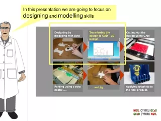
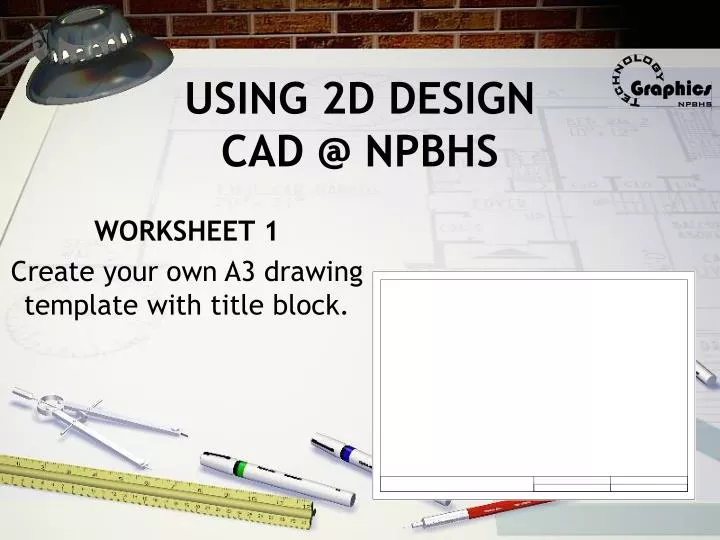
USING 2D DESIGN CAD @ NPBHS. WORKSHEET 1 Create your own A3 drawing template with title block. OPENING 2D DESIGN ON NPBHS WINDOWS NETWORK. OPEN PROGRAM. A3 PAGE SIZE. Starting a 10mm perimeter border. Check O.K or press return. Select rectangle shape tool. 10 mm

E N D
USING 2D DESIGNCAD @ NPBHS WORKSHEET 1 Create your own A3 drawing template with title block.
OPENING 2D DESIGN ON NPBHS WINDOWS NETWORK OPEN PROGRAM
Starting a 10mm perimeter border Check O.K or press return Select rectangle shape tool 10 mm X & Y absolute settings
Create a 10mm perimeter border Finish size of border at these absolute settings
Finished border A3 page = 420mm297mm Now has a border 10mm set in all the way around.
Title Block • To create a title block 26mm high and the width of the border select the straight line tool to start at Abs value 10,36 – finishing at 410,36.
To create the 4 panels on the on the RHS of the title block select the straight line tool to start at Abs value 210,10 – finishing at 210,36. • And again at Abs value 310,10 – finishing at 310,36. • The horizontal line to complete the title block starts at Abs value 210,23 – finishing at 410,23.
Saving your work to file Ensure that you save drawings to a location that you can retrieve/find them again next time i.e. into your network folder with an appropriate name.
Personalising your page - lines We can set the line thickness to match the line weight that you would have done this as a technical drawing with instruments. With 2D design you can match all of the drawing conventions to NZ 1100 drafting stds required for NCEA
Personalising your page - text Click the layers button & select layer 2 for the text to be located on. Add a description of what is on this layer.
Personalising your page – text size The default font is Arial – this already set to the technical drawing stds. Set the height to be either 5 or 3mm depending on what it is describing. • Press o.k. to activate the text entry box. • Type in capitals.
Personalising your page – text location Use the select tool to highlight and drag the text into location. (Click on the middle handle)
Personalising your page – text Info • This is generic information that can be altered for any drawing. • Because you have set it on a new layer, this layer can be switched off if you do not require it, or want to over ride it on a new layer!
Personalising your page - 3rd Angle symbol Click on the layers button, select layer 3 as the current layer & give it an suitable description.
Personalising your page - 3rd Angle symbol • Construct a centre line • 5mm pitch • Line width = fine
Select the line tool & click anywhere on the page. • Click the Abs button to now be Rel (relative) plotting the line to go along 34mm & up 0mm – o.k. • Select construction points on LHS palette. • Select the attach tool on the RHS palette. • Attach a construction node onto the end of the centre line.
Without changing the setting now set the Rel sizes to make a construction point 7mm from the end of the line. Double click on the line tool, bringing up settings for length & angle – 7,90.
Attach the new line to the const point Select the new line Use the attach tool on each end of the horizontal line to create the mirror line.
Put line type back to an outline. Make 2 circles attached to the Centre lines – r5mm, r2.5mm.
Construction Nodes for the Elevation Length.
Attach the centre of the 5mm line to the construction point. • Repeat for the 10mm line.
3rd Angle symbol Connect the ends of each line.
Completed Worksheet! SAVE
APPENDIX 2D DESIGN CO-ORDINATES ORIENTATION


![[Auto]CAD Basics: Foundations and 2D drawings](https://cdn1.slideserve.com/2898817/slide1-dt.jpg)