Download
1 / 36
570 likes | 1.2k Views
Chapter 6. Plane Stress / Plane Strain Problems. Element types: Line elements (spring, truss, beam, frame) – chapters 2-5 2-D solid elements – chapters 6-10 3-D solid elements – chapter 11 Plate / shell elements – chapter 12. 2-D Elements. Triangular elements – plane stress/plane strain:

E N D
Chapter 6. Plane Stress / Plane Strain Problems Element types: Line elements (spring, truss, beam, frame) – chapters 2-5 2-D solid elements – chapters 6-10 3-D solid elements – chapter 11 Plate / shell elements – chapter 12
2-D Elements Triangular elements – plane stress/plane strain: CST – “constant strain triangle” – chap. 6 LST – “linear strain triangle” – chap. 8 Axisymmetric elements – chap. 10 Isoparametric elements – chap. 11 4-node quadrilateral element (linear interpolation) 8-node quadrilateral element (quadratic interpolation)
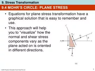
2-D Stress States Matrix form:
Displacements and Strains Displacement field Strains
Stress-Strain Relations Recall: E – Young’s modulus • - Poisson’s Ratio G – Shear modulus
Stress-Strain Relations (cont.) • Plane stress • Plane strain • Note, in both cases
Derivation of “Constant Strain Triangle” (CST) Element Equations Step 1 – Select element type Note – x-y are global coordinates (will not need to transform from local to global
Displacement Interpolation Assume “bi-linear” interpolation – guarantees that edges remain straight => inter-element compatibility
Displacement Interpolation (cont.) As before, rewrite displacement interpolation in terms of nodal displacements (see text for details) where
Displacement Interpolation (cont.) Graphically:
Step 3 – Strain-Displacement and Stress-Strain Relations From which it can be shown
Strain-Displacement Relations (cont.) • Note – the strain within each element is constant (does not vary with x & y) • Hence, the 3-node triangle is called a “Constant Strain Triangle” (CST) element
3x1 3x3 3x6 6x1 Stress-Strain Relations
6x6 6x3 3x3 3x6 Step 4 – Derive Element Equations which will be used to derive
Derive Element Equations (cont.) Strain energy:
Derive Element Equations (cont.) Potential energy of applied loads:
Derive Element Equations (cont.) Potential energy:
Derive Element Equations (cont.) Substitute to yield
Derive Element Equations (cont.) Apply principle of minimum potential energy To obtain
Derive Element Equations (cont.) Element stiffness matrix
Steps 5-7 5. Assemble global equations 6. Solve for nodal displacements 7. Compute element stresses (constant within each element)
CST Element Stiffness Matrix where [B] – depends on nodal coordinates [D] – depends on E, See text for details
Body and Surface Forces Replace distributed body forces and surface tractions with work equivalent concentrated forces. { fs } { fb }
Work Equivalent Concentrated Forces – Body Forces For a uniformly distributed body forces Xb and Yb:
Work Equivalent Concentrated Forces – Surface Forces For a uniform surface loading, p, acting on a vertical edge of length,L, between nodes 1 and 3:
Example 6.2 - Solution Element 2 Element 1
In-class Abaqus Demonstrations • Example 6.2 • Finite width plate with circular hole (ref. “Abaqus Plane Stress Tutorial”)
Chapter 7 - Practical Considerations in Modeling; Interpreting Results; and Examples of Plane Stress/Strain Analysis Discussion of Example 6.2: