Download
1 / 56
580 likes | 799 Views
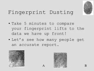
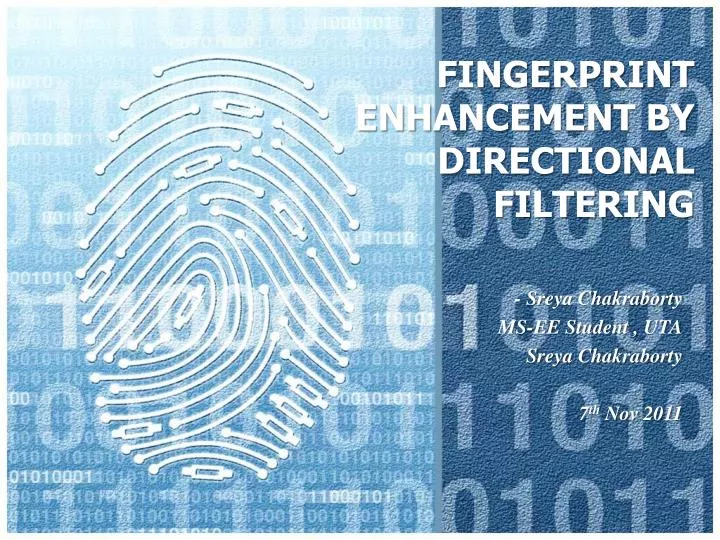
FINGERPRINT ENHANCEMENT BY DIRECTIONAL FILTERING. - Sreya Chakraborty MS-EE Student , UTA Sreya Chakraborty 7 th Nov 2011. Fingerprint. Introduction. Why enhancement?

E N D
FINGERPRINT ENHANCEMENT BY DIRECTIONAL FILTERING - Sreya Chakraborty MS-EE Student , UTA SreyaChakraborty 7th Nov 2011
Introduction • Why enhancement? • Several stages of processing take place when an Automated Fingerprint Identification System (AFIS) is used to match an unknown fingerprint 1) Enhanced 2) Encoded 3) Matching 4) Verification
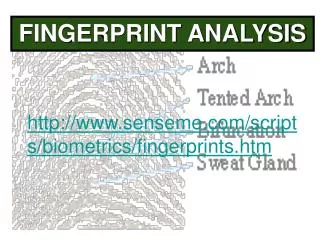
Flow of the presentation: • Various Biometrics • The need for Enhancement • Various previous work • The orientation used in the thesis • The Gabor filter technique
Background • Biometrics categories: • Physical biometrics • Face • Hand Geometry • Iris • Fingerprint
Background Commercial three dimensional scanner [24] Facial recognition [24]
Background • Behavioral biometrics • Gait • Handwriting • Signature • Speech • Multimodal systems
Background Handwriting sample Multimodal system
Need for fingerprint enhancement • It is obvious that fingerprints are the most widely applied biometric identifiers. With the help of high performance computers, Automatic Fingerprint Identification Systems (AFIS) have gradually replaced human experts in fingerprint recognition as well as classification. However, fingerprint images contain noises caused by factors such as dirt, grease, moisture, and poor quality of input devices and are one of the noisiest image types, according to O’Gorman [6]. Therefore, fingerprint enhancement has become a necessary and common step after image acquisition in the AFIS.
Scanning Device Fingerprint scanner
Steps for fingerprint enhancement A flowchart of the proposed fingerprint enhancement algorithm [3]
Normalization Normalized image [7]
Minutiae Extraction • The following steps (in no particular order) are the basic steps that may be utilized before a template can be created. • Image binarization • Ridge orientation estimation • Ridge smoothing • Image enhancement
Previous work • In the method used by Hill [17] the orientation field is generated based on singular points according to the model in [19].
Previous work • The proposed algorithm of Ross et al [18] utilizes a set of three minutiae points (minutiae triplet) to predict the orientation of a triangular fingerprint region defined by the triplet. In the formulation a minutia point is represented as (x; y; θ), with (x, y) being its spatial location and θ its orientation. The algorithm for generating the orientation map has three main stages: 1) triplet generation, 2) orientation estimation, and 3) averaging orientation map.
Previous work • Triplet generation: • Consider a minutiae template, M, of a fingerprint containing N minutiae points given by, M = {m1,m2,…..mN} where mi= {xi,yi, θi}. A set of 3 minutiae points {mi}i=1,2,3, characterized by a triangle with sides {Li}i=1,2,3 and interior angles {Φi}i=1,2,3 • Lmin≤ Li≤ Lmax , for all i=1,2,3. This ensures that the perimeter of the triangle traverses a compact region, thus, avoiding the large global variability observed in the fingerprints of most classes. • θdif≤ θminwhere θdif = maxi=1,2,3 (θi- θmed) and θmedis the median of { θi}i=1,2,3. This ensures that the orientations of component minutiae points are within a small interval. • θi≤ θmin , for all i=1,2,3. This ensures that “narrow" triangles subtending a very small area are avoided.
Previous work Deducing the orientation field from minutiae distribution. (a) A single minutiae triplet. (b) Forming triplets across the minutiae distribution. (c) Estimated orientation field using minutiae triplet information [18]
Previous work • Consider a pixel P(x,y) located inside the triangular region defined by a triplet. Let be the Euclidean distances of this pixel • from the entire ith vertex. The orientation of the pixel P, is then estimated as [18].
Previous work • Cappelli et al [20] proposed a technique to directly reconstruct the grayscale image from minutiae. The orientation field is estimated by fitting a modified model initially proposed in [21] to the minutiae directions. • Feng, and Jain [22] proposed a novel approach to fingerprint reconstruction from minutiae template which first reconstructs a phase image from the minutiae template and then converts the phase image into the grayscale image. The advantages of this approach over existing approaches to fingerprint reconstruction [17], [18], [20] are: • A complete fingerprint can be reconstructed and 2. The reconstructed fingerprint contains very few spurious minutiae
Algorithm for estimating LRO at a point x= 0, 1, 2… 31 where
Algorithm for estimating LRO at a point Projections of a window of fingerprint image data. The projections which exhibit the greatest variation correspond to the orientation of the ridges within the window. Eight projection are shown here [2].
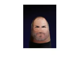
Gabor Filter Car image Lossy image translation
Gabor filter Building image Rotated image
Gabor filter • Equation 1: • Equation 2: • Equation 3:
Gabor filter • substituting equation 1 and equation 2 in equation 3: • Since exp[jθ] = cosθ + jsinθ
Gabor filter One dimensional Gabor filter [29]
Results Original image 1 Gabor filtered image1
Results Histogram of the original image1 Histogram of the Gabor filtered image1
Results Histogram equalized of the Gabor filtered image1
Results Original image 2 Gabor filtered image2
Results Histogram of the original image2 Histogram of the Gabor filtered image2
Results Histogram equalized of the Gabor filtered image2
Results Original image 3 Gabor filtered image3
Results Histogram of the original image3 Histogram of the Gabor filtered image3
Results Histogram equalized of the Gabor filtered image3
Results Original image 4 Gabor filtered image4
Results Histogram of the original image4 Histogram of the Gabor filtered image4
Results Histogram equalized of the Gabor filtered image4
Results Original image5 Gabor filtered image5
Results Histogram of the original image5 Histogram of the Gabor filtered image5
Results Histogram equalized of the Gabor filtered image5
Results Original image 6 Gabor filtered image6
Results Histogram of the original image6 Histogram of the Gabor filtered image6
Results Histogram equalized of the Gabor filtered image6
Conclusions • In this thesis Gabor filter is used for fingerprint enhancement technique. Because of its frequency selective and orientation selective properties it is very effective for fingerprint enhancement. A window of size 32 by 32 pixels is centered at the point where the LRO is to be found. This window is rotated to 16 different orientations. The projections which exhibit the greatest variation corresponds to the orientation of the ridges within the window. The primary advantage of the approach is improved translation and rotation invariance.
Appendix An even symmetric Gabor filter has the following general form in the spatial domain:
Appendix Fig A.1 The range of x and y goes from -15 to 15 to produce the Gabor kernel
Appendix Fig A.3 Gabor filters of size 16 × 16 by 8 orientations and 5 Resolutions (real part).