Download
1 / 43
530 likes | 648 Views
ELECTRICAL PROPERTIES OF MATERIAL. MDM. HANA ABDULL HALIM. INTRODUCTION. Objective: To explore the electrical properties of materials, which is their response to an applied electric field. ELECTRICAL CONDUCTION. OHM’S LAW; V = IR Resistivity ᵨ = RA / l Conductivity s = 1 / ᵨ

E N D
ELECTRICAL PROPERTIES OF MATERIAL MDM. HANA ABDULL HALIM
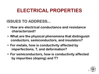
INTRODUCTION • Objective: To explore the electrical properties of materials, which is their response to an applied electric field.
ELECTRICAL CONDUCTION • OHM’S LAW; V = IR • Resistivityᵨ= RA /l • Conductivitys = 1 / ᵨ • Solidmaterialsexhibits an amazing range of electrical conductivities. In fact, one way of classifyingsolidmaterialsisaccording to the easewithwhichtheyconduct an electriccurrent; conductors, semiconductors and insulators
ELECTRONIC AND IONIC CONDUCTION • Withinmostsolidmaterialsa current arises from the flow of electrons : Electronic Conduction • For ionicmaterials a net motion of charged ions is possible thatproduces a current : Ionic Conduction
Room-Temperature ElectricalConductivities for Nine CommonMetals and Alloys
Conductivity: Comparison CERAMICS Soda-lime glass 10 -9 Concrete 10 -13 Aluminum oxide <10 SEMICONDUCTORS POLYMERS -14 -4 Polystyrene <10 Silicon 4 x 10 -10 -15 -17 -11 0 Polyethylene 10 -10 -10 Germanium 2 x 10 -6 GaAs 10 insulators semiconductors -1 -1 • = ( - m) • Room T values (Ohm-m) METALS conductors 7 Silver 6.8 x 10 7 Copper 6.0 x 10 7 Iron 1.0 x 10
Example: Conductivity Problem 100m < 1.5V 2.5A 7 -1 6.07 x 10 (Ohm-m) What is the minimum diameter (D) of the wire so that DV < 1.5 V? 100m - e I = 2.5A + - Cu wire DV Solve to get D > 1.87 mm
TRY IT YOURSELF! (a) Compute the electrical conductivity of a 7.0-mm diameter cylindrical silicon specimen 57 mm long in which a current of 0.25A passes in an axial direction. A voltage of 24 V is measured across two probes that are separated by 45 mm. (b) Compute the resistance over the entire 57 mm of the specimen.
ENERGY BAND STRUCTURES IN SOLIDS • In all conductors, semiconductors and isulators, onlyelectronic conduction exists, and the magnitude of the electrical conductivityisstronglydependent on the number of electronsavailable. • However, not all electronswillaccelerate in the presence of an electricfield. • The number of electronsavailable for electrical conduction in a particularmaterialisrelated to the arrangement of electronlevels.
BAND STRUCTURE • Valence band – filled – highest occupied energy levels • Conduction band – empty – lowest unoccupied energy levels Conduction band valence band
BAND STRUCTURE • The various possible electron band structures in solids at 0 K. • The electron band structure found in metals such as copper, in which there are available electron states above and adjacent to filled states, in the same band. • (b) The electron band structure of metals such as magnesium, wherein there is an overlap of filled and empty outer bands. • The electron band structure characteristic of insulators; the filled valence band is separated from the empty conduction band by a relatively large band gap ( >2 eV). • The electron band structure found in the semiconductors, which is the same as for insulators except that the band gap is relatively narrow (<2 eV).
- + - Energy Energy empty band empty GAP band partly filled filled valence valence band band filled states filled states filled filled band band CONDUCTION & ELECTRON TRANSPORT • Metals (Conductors): -- Thermal energy puts many electrons into a higher energy state. • Energy States: -- for metals nearby energy states are accessible by thermal fluctuations.
Energy States: Insulators &Semiconductors • Semiconductors: -- Higher energy states separated by smaller gap (< 2 eV). Energy Energy empty empty band band ? GAP GAP filled filled valence valence band band filled states filled states filled filled band band • Insulators: -- Higher energy states not accessible due to gap (> 2 eV).
CHARGE CARRIERS-METALS Two charge carrying mechanisms Electron – negative charge Hole – equal & opposite positive charge Move at different speeds - drift velocity Higher temp. promotes more electrons into the conduction band as T Electrons scattered by impurities, grain boundaries, etc.
CHARGE CARRIERS-SEMICONDUCTOR AND INSULATOR For an insulator or semiconductor, occupancy of electron states (a) before (b) after an electron excitation from the valence band into the conduction band, in which both a free electron and a hole are generated.
ELECTRON MOBILITY A force is brought to bear on the free electrons; When an electric field is applied and they all experience an acceleration in a direction opposite to that of the field, by virtue of their negative charge. Current increasing with time and reaches a constant value indicating that there exist “frictional force”. The scattering phenomenon is manifested as a resistance to the passage of an electric current. Drift Velocity µe – Electron Mobility The average electron velocity in the direction of the force imposed by the applied field. It is directly proportional to the electric field Path of an electron that is deflected by scattering events. Conductivity
EXERCISE (a) Calculate the drift velocity of electrons in silicon at room temperature and when the magnitude of the electric field is 500 V/m. (b) Under these circumstances, how long does it take an electron to traverse a 25-mm length of crystal?
BAND GAP ENERGIES, ELECTRON AND HOLE MOBILITIES, ANDINTRINSIC ELECTRICAL CONDUCTIVITIES AT ROOM TEMPERATURE FOR SEMICONDUCTING MATERIALS
ELECTRICAL RESISTIVITY OF METALS Metals have high conductivities because of the large numbers of free electrons that have been excited into empty states above the Fermi energy. Thus, n has a large value in the conductivity expression Room-Temperature Electrical Conductivities for Nine Common Metals and Alloys
ELECTRICAL RESISTIVITY OF METALS The electrical resistivity versus temperature for copper and three copper–nickel alloys, one of which has been deformed. Thermal, impurity, and deformation contributions to the resistivity are indicated at -100ºC
ELECTRICAL RESISTIVITY OF METALS Room-temperature electrical resistivity versus composition for copper–zinc alloys.
ELECTRICAL RESISTIVITY OF METALS Total resistivity of a metal is the sum of the contributions from thermal vibrations, impurities and plastic deformation Influence of Temperature ci - Impurity Concentration Influence of Impurities A - Composition-independent Constant
6 r Cu + 3.32 at%Ni 5 Ohm-m) Cu + 2.16 at%Ni 4 Resistivity, deformed Cu + 1.12 at%Ni 3 -8 Cu + 1.12 at%Ni 2 (10 1 “Pure” Cu 0 -200 -100 0 T (°C) METALS: RESISTIVITY VS T, IMPURITIES • Imperfections increase resistivity -- grain boundaries -- dislocations -- impurity atoms -- vacancies These act to scatter electrons so that they take a less direct path. • Resistivity increases with: -- temperature -- wt% impurity -- %CW = thermal + impurity + deformation
180 50 r 160 Ohm-m) 40 140 125 30 30 120 Resistivity, Yield strength (MPa) -8 20 100 (10 21 wt%Ni 10 80 0 60 0 10 20 30 40 50 0 10 20 30 40 50 wt. %Ni, (Concentration C) wt. %Ni, (Concentration C) From step 1: CNi = 21 wt%Ni ESTIMATING CONDUCTIVITY • Question: -- Estimate the electrical conductivity of a Cu-Ni alloy that has a yield strength of 125 MPa.
Energy s electrical conductivity, empty -1 band ? (Ohm-m) GAP 4 10 electrons can cross gap at higher T 3 10 filled valence 2 10 band filled states 1 10 filled 0 10 pure band (undoped) -1 10 material Si Ge GaP CdS band gap (eV) 1.11 0.67 2.25 2.40 -2 10 1 000 10 0 50 T(K) PURE SEMICONDUCTORS: CONDUCTIVITY VS T • Data for Pure Silicon: -- s increases with T -- opposite to metals
DIELECTRIC BEHAVIOR A dielectric material is one that is electrically insulating (nonmetallic) and exhibits or may be made to exhibit an electric dipole structure; that is, there is a separation of positive and negative electrically charged entities on a molecular or atomic level. Dipole interaction with electric field, dielectric materials are utilized in capacitor ϵ - permittivity ϵr Dielectric Constant
DIELECTRIC BEHAVIOR A parallel-plate capacitor • when a vacuum is present • when a dielectric material is present
DIELECTRIC CONSTANTS AND STRENGTHS FOR SOME DIELECTRIC MATERIALS
POLARIZATION p - electric dipole moment q - the magnitude of each dipole charge d - the distance An electric dipole generated by two electric charges (of magnitude q) separated by the distance d and the associated polarization vector p
POLARIZATION • Imposed forces (and torque) acting on a dipole by an electric field • (b) Final dipole alignment with the field
POLARIZATION (a) The charge stored on capacitor plates for a vacuum (b) The dipole arrangement in an unpolarized dielectric (c) the increased charge storing capacity resulting from the polarization of a dielectric material.
POLARIZATION D - Dielectric Displacement P - Polarization
PRIMARY AND DERIVED UNITS FOR VARIOUS ELECTRICAL PARAMETERSAND FIELD VECTORS
TYPES OF POLARIZATION • Electronic Polarization Electronic polarization may be induced to one degree or another in all atoms. It results from a displacement of the center of the negatively charged electron cloud relative to the positive nucleus of an atom by the electric field. This polarization type is found in all dielectric materials and, of course, exists only while an electric field is present. Electronic polarization that results from the distortion of an atomic electron cloud by an electric field
Types Of Polarization • Ionic Polarization Ionic polarization occurs only in materials that are ionic. An applied field acts to displace cations in one direction and anions in the opposite direction, which gives rise to a net dipole moment. The magnitude of the dipole moment for each ion pair pi is equal to the product of the relative displacement diand the charge on each ion, or Ionic polarization that results from the relative displacements of electrically charged ions in response to an electric field
Types Of Polarization • Orientation Polarization The third type, orientation polarization, is found only in substances that possess permanent dipole moments. Polarization results from a rotation of the permanent moments into the direction of the applied field.This alignment tendency is counteracted by the thermal vibrations of the atoms, such that polarization decreases with increasing temperature. Response of permanent electric dipoles (arrows) to an applied electric field, producing orientation polarization.
FREQUENCY DEPENDENCE OFTHE DIELECTRIC CONSTANT • In many practical situations the current is alternating (ac); that is, an applied voltage or electric field changes direction with time Dipole orientations for (a) one polarity of an alternating electric field and (b) for the reversed polarity.
FREQUENCY DEPENDENCE OFTHE DIELECTRIC CONSTANT • With each direction reversal, the dipoles attempt to reorient with the field, in a process requiring some finite time. For each polarization type, some minimum reorientation time exists, which depends on the ease with which the particular dipoles are capable of realignment. A relaxation frequency is taken as the reciprocal of this minimum reorientation time. • The absorption of electrical energy by a dielectric material that is subjected to an alternating electric field is termed dielectric loss. This loss may be important at electric field frequencies in the vicinity of the relaxation frequency for each of the operative dipole types for a specific material. A low dielectric loss is desired at the frequency of utilization.
FREQUENCY DEPENDENCE OFTHE DIELECTRIC CONSTANT Variation of dielectric constant with frequency of an alternating electric field. Electronic, ionic and orientation polarization contributions to the dielectric constant are indicated
DIELECTRIC STRENGTH When very high electric fields are applied across dielectric materials, large numbers of electrons may suddenly be excited to energies within the conduction band. As a result, the current through the dielectric by the motion of these electrons increases dramatically; sometimes localized melting, burning, or vaporization produces irreversible degradation and perhaps even failure of the material. This phenomenon is known as dielectric breakdown. The dielectric strength, sometimes called the breakdown strength, represents the magnitude of an electric field necessary to produce breakdown.
DIELECTRIC MATERIALS A number of ceramics and polymers are utilized as insulators and/or in capacitors. Many of the ceramics, including glass, porcelain, steatite and mica, have dielectric constants within the range of 6 to 10. These materials also exhibit a high degree of dimensional stability and mechanical strength. Typical applications include powerline and electrical insulation, switch bases, and light receptacles. The titania (TiO2) and titanate ceramics, such as barium titanate (BaTiO3), can be made to have extremely high dielectric constants, which render them especially useful for some capacitor applications. The magnitude of the dielectric constant for most polymers is less than for ceramics, since the latter may exhibit greater dipole moments: values for polymers generally lie between 2 and 5. These materials are commonly utilized for insulation of wires, cables, motors, generators, and so on, and, in addition, for some capacitors.
DIELECTRIC CONSTANTS AND STRENGTHS FOR SOME DIELECTRIC MATERIALS