Download
1 / 36
360 likes | 481 Views
Combinatorial Representations for Analysis and Conceptual Design in Engineering. Dr. Offer Shai Department of Mechanics, Materials and Systems Faculty of Engineering Tel-Aviv University. Solving a problem simply means representing it so as to make the solution transparent. Herbert Simon.

E N D
Combinatorial Representations for Analysis and Conceptual Design inEngineering Dr. Offer Shai Department of Mechanics, Materials and Systems Faculty of Engineering Tel-Aviv University
Solving a problem simply means representing it so as to make the solution transparent Herbert Simon
Solving a problem simply means representing it so as to make the solution transparent It was found that: the proposed research work implements Simon's vision on Conceptual Design and Research. Herbert Simon
Solving a problem simply means representing it so as to make the solution transparent Method: Transforming Engineering Design Problem into another Field, where the solution might already exist Herbert Simon
Solving a problem simply means representing it so as to make the solution transparent Solid Mathematical Basis: Combinatorial Representations based on Graph and Matroid Theories Herbert Simon
F F F F F F F Graph Representations - Definition Graph Representation Structure and Geometry Voltage, absolute velocity, pressure Relative velocity, deformation Force, Current, Moment Engineering system Current approach employs mathematical models based on graph theory to represent engineering systems
Input shaft Output shaft 1 4 C D A 2 5 3 6 B D C Overrunning Clutches Unidirectional Gear Train out= |in| Consider two engineering systems from the fields of mechanics and electronics.
1 4 C D A 2 5 3 6 B D C Building the graph representation of the system Graph Representation of the system maps its structure, the behavior and thus also its function
A 1 4 Input Source C D A C D 2 5 3 6 B D C B Output Electronic Diode Bridge Circuit Vout= |Vin| Consider two engineering systems from the fields of mechanics and electronics.
A 1 4 C D A C D 2 5 3 6 B D C B Building the graph representations of the systems Graph Representation of the system maps its structure, the behavior and thus also its function
A 1 4 C D A C D 2 5 3 6 B D C B Building the graph representations of the systems The two engineering systems possess identical graph representations
Solving Design Problem FR’={ out= | in| } Graph Representation FR={ out= |in| } FR’’={ Vout= | Vin| } Mechanics Electronics We shall now consider a hypothetical design problem for inventing the unidirectional gear train
A C D B Solving Design Problem FR’={ out= | in| } Graph Representation FR={ out= |in| } FR’’={ Vout= | Vin| } Mechanics Electronics In electronics there is a known device satisfying this functional requirement – diode bridge circuit
Trusses (Determinate) (Indeterminate) Common Representation Design Technique upon the map of graph representations
Designing an active torque amplifier FR’1={ out= in } FR’2={ Fout= kFin } Graph Representation FR1={ out= in} FR2={ Tout= kTin; k>>1} FR’’1={ Vout= Vin } FR’’2={ Iout= kIin } Mechanics Electronics Solving a real design problem through by means of the approach
Designing an active torque amplifier Solving a real design problem by means of the approach
Designing an active torque amplifier FR’1={ out= in } FR’2={ Fout= kFin } Graph Representation FR1={ out= in} FR2={ Tout= kTin; k>>1} FR’’1={ Vout= Vin } FR’’2={ Iout= kIin } Mechanics Electronics Solving a real design problem by means of the approach
Output shaft Screw thread Input shaft Engine Work principle of an active torque amplifier The four working modes of the active torque amplifier mechanism
Another Transformation Alternative Graph Representation
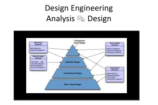
Design through mathematically related representations Graph Representation Graph Representation of another type Statics Kinematics Same approach can be applied to graph representation
Graph Representation Graph Representation of another type FR’’={ out>> in } FR’={ Fout>>Fin } FR’’’={ out>> in } FR={ Pout>>Fin } Statics Kinematics Designing a force amplifying beam system
0 G B A B A 1 2 3 4 5 B A B A C G C I II III IV C G C G G 0 2 4 3 5 C C B B wout 1 A A G G win Graph Representation Graph Representation of another type FR’’={ out>> in } FR’={ Fout>>Fin } FR’’’={ out>> in } FR={ Pout>>Fin } Statics Kinematics Known gear train satisfying this requirement is the gear train employed in electrical drills.
1. Duality relations 2. Duality relations for checking truss rigidity 3. Duality relations for finding special properties 4 Identification of singular configurations 5 Devising new engineering concepts – face force 6 Devising new engineering concepts – equimomental lines 7 Multidisciplinary engineering education 8 Topics on the edges between statics and kinematics
L K 11 7 0 10 A P F 2 P 12 2 P 7 J 1 B 12 I H 8 9 9 11 C 10 8 1 D 6 L K 5 2 4 3 G I II H P A B D E C F 1 I J K L P 2 O DUALITY RELATIONS 1 Dual Graph Representation 2 Dual Robot system Statical platform system 3 4 5 6 7 8 Graph Representation Applying the graph theoretical duality principle to the graph representations yielded new relations between systems belonging to different engineering fields
12 12 2 2 4 8 4 3 3 7 5 9 1 7 1 9 5 6 6 10 10 11 11 8 Rigid ???? 2 ’ 12 ’ 4 ’ 8 ’ 3 ’ 2 ’ 1 ’ 7 ’ 5 ’ 9 ’ 12 ’ 8 ’ 6 ’ 4 ’ 10 ’ 3 ’ 9 ’ 7 ’ 1 ’ 1 1 ’ 5 ’ 6 ’ 10 ’ R’ 11 ’ R’ Definitely locked !!!!! DUALITY RELATIONS 1 2 3 4 5 6 Due to links 1 and 9 being located on the same line 7 8 By means of the duality transformation, checking the rigidity of trusses can be replaced by checking the mobility of the dual mechanisms
DUALITY RELATIONS 1 2 Serial Robot Locked configuration 3 4 5 6 7 known singular position 8 The Dual Stewart Platform The dual systems can be employed for detection of special properties of the original system
IDENTIFICATION OF SINGULAR CONFIGURATIONS 1 2 3 Given mechanism topology 4 5 6 7 8 One of the results of applying the approach – a new method for finding all dead center positions for a given mechanism topology
DIVISING NEW ENGINEERING CONCEPTS 1 2 3 4 5 6 7 8 Transforming known engineering concepts from one engineering field through graph representations to another, frequently yields new, useful concepts.
DIVISING NEW ENGINEERING CONCEPTS 1 FACE FORCE 2 3 4 5 6 7 8 The concept of linear velocity has been transformed from kinematics to statics. The result: a new statical variable combining the properties of force and potential
DIVISING NEW ENGINEERING CONCEPTS 1 FACE FORCE 2 3 4 5 6 7 8 The concept of linear velocity has been transformed from kinematics to statics. The result: a new statical variable combining the properties of force and potential
DIVISING NEW ENGINEERING CONCEPTS 1 Equimomental line 2 3 Kinematics Statics 4 For any two bodies moving in the plane there exists a point were their velocities are equal – relative instant center For any two forces acting in the place there exists a line, so that both forces apply the same moment upon each point on this line 5 6 7 8 The concept of relative instant center from kinematics has been transformed to statics. Result: new locus of points in statics - equimomental line
DIVISING NEW ENGINEERING CONCEPTS 1 Equimomental line 2 3 Kinematics Statics 4 5 6 Instant center – long known kinematical tool for analysis and synthesis of kinematical systems Equimomental line – completely new tool for analysis and synthesis of statical systems 7 8 The concept of relative instant center from kinematics has been transformed to statics. Result: new locus of points in statics - equimomental line
Multidisciplinary engineering education 1 2 3 4 5 6 7 8 The students are first taught the graph representations, their properties and interrelations. Only then, on the basis of the representations they are taught specific engineering fields.
Topics on the edge between statics and kinematics 1 2 3 4 5 6 7 8 Studying deployable structures requires consideration of both kinematical (during deployment) and statical (in locked position) aspects
Thank you!!! For more information contact Dr. Offer Shai Department of Mechanics, Materials and Systems Faculty of Engineering Tel-Aviv University This and additional material can be found at: http://www.eng.tau.ac.il/~shai