Download
1 / 80
800 likes | 976 Views
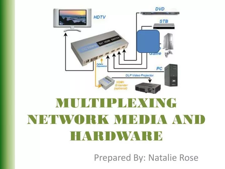
MULTIPLEXING NETWORK MEDIA AND HARDWARE . Prepared By: Natalie Rose. MULTIPLEXING.

E N D
MULTIPLEXING NETWORK MEDIA AND HARDWARE Prepared By: Natalie Rose
MULTIPLEXING If the bandwidth of a medium linking two devices is greater than the bandwidth needed then the link can be shared using Multiplexing. Multiplexing is the set of techniques that allows the (simultaneous) transmission of multiple signals across a single data link. As data and telecommunications use increases, so does traffic. Types of Multiplexing: • Frequency-Division Multiplexing • Wavelength-Division Multiplexing • Synchronous Time-Division Multiplexing • Statistical Time-Division Multiplexing
QUESTION #1 Assume that a voice channel occupies a bandwidth of 4 kHz. We need to combine three voice channels into a link with a bandwidth of 12 kHz, from 20 to 32 kHz. Show the configuration, using the frequency domain. Assume there are no guard bands.
QUESTION #1 SOLUTION We shift (modulate) each of the three voice channels to a different bandwidth, as shown in Figure 1. We use the 20- to 24-kHz bandwidth for the first channel, the 24- to 28-kHz bandwidth for the second channel, and the 28- to 32-kHz bandwidth for the third one. Then we combine them.
TIME DIVISION MULTIPLEXING(TDM) Combines several low-rate digital channels into one high-rate one.
GUIDED MEDIA Guided media, which are those that provide a conduit from one device to another, include twisted-pair cable, coaxial cable, and fiber-optic cable. CATEGORIES Twisted-Pair CableCoaxial CableFiber-OpticCable
TIA/EIA 568 • The first major standard describing a structured cabling system for computer networks was the TIA/EIA 568-A in 1995. EIA is the Electronics Industries Alliance a trade organization that lobbies for the interests of manufacturers of electronics related equipment. TIAstands for the Telecommunications Industry Association, which is a trade organization that represents the interests of the telecommunications industry.
EIA/TIA 568-A Addendum 5 • The most important addendum to the EIA/TIA 568-A standard was Addendum 5, published in 1999. • This addendum defined the transmission performance specifications for 4-pair 100 ohm Category 5e twisted-pair cabling. • This is the type of cabling recommended for use in today’s computer networks. (Actually CAT6 is the currently being recommended)
Campus Network • The EIA/TIA 568-A standard defined the minimum requirements for the internal telecommunications wiring in buildings and between structures in a campusnetwork. • A campus network consists of interconnected LANs within a limited geographic area such as a college campus, a military base, or a group of commercial buildings.
EIA/TIA 568-B • in the year 2000 a new standard, the EIA/TIA 568-B was published. The three parts of the EIA/TIA 568-B are as follows: • EIA/TIA-568-B.1 Commercial Cabling • EIA/TIA-568-B.2 Twisted Pair Media • EIA/TIA-568-B.3 Optical Fiber Cabling
T568A / T568B Within the EIA/TIA568B standard are the wiring guidelines T568A and T568B. These wiring guidelines specify the color of wire that connects to what pin on the connector. The specification of the wire color that connects to what pin is called a color map. The color maps specified by the T568A and T568B wiring guidelines are shown.
The placement of the wire pairs in the RJ-45 modular plug are shown for the T568A standard. The pin numbers for the RJ-45 modular plug are shown at the top. A wire color table is also provided next to the pictures of the cable for reference. In the T568A wire color scheme, a white-green wire connects to pin 1, the wire color green connects to pin 2, and the wire color connected to pin 3 is white-orange and so on.
The placement of the wire pairs in the RJ-45 modular plug are shown for the T568B standard. The pin numbers for the RJ-45 modular plug are shown at the top. A wire color table is also provided next to the pictures of the cable for reference. In the T568B wire color scheme, a white-orange wire connects to pin 1, the wire color orange connects to pin 2, and the wire color connected to pin 3 is white-green and so on.
Assembling the Straight-through Patch Cable • This section presents a technique for assembling a straight-through patch cable. • In a straight-through patch cable, the wire pairs in the cable connect to the same pin numbers on each end of the CAT5/5e/6 patch cable. • A CAT5e patch cable with RJ-45 modular plugs is shown.
To Begin • Prior to terminating the cable, inspect the cable for any damage that might have occurred in installation. • Possible damage to look for includes nicked or cut wires, and possible stretching of the cable. • Measure the cable to length, add about six inches extra and cut the wire. It is good to have a little extra in case you make an error in installation and have to redo the termination. You can’t splice CAT5/5e/6 twisted-pair cable!
Strip approximately ¾ inch of the cable jacket from the end of the cable using a cable stripper. Notice that the stripper is positioned about ¾ inch from the end of the cable. The cable insulation is removed by rotating the insulation stripper around the wire until the wire jacket is loose and then easily removed. Note: these tools must be periodically adjusted so that the blade cuts through the outer insulation. If the blades are set to deep they will nick the wires and the process must be repeated. The damages portion of the cable must be cut-away. Nicking of the insulation of the twisted pair wires is not permitted.
Sort the wire pairs so that they fit into the connector and orient the wire in the proper order for either T568A or T568B as shown in Figures 2(a) and 2(b) in the text. (T568A order is shown)
Insert the wires onto the RJ-45 modular plug as shown. Push the wires into the connector until the ends of each wire can be seen through the clear end of the connector. Note: Now is the time to verify that the wire order is correct. The wires are visible through the plastic connector as shown. Clip the wires so that they are even.
Next, a crimping tool is used to crimp the wires onto the RJ-45 plug. The RJ-45 plug is inserted into the crimping tool until it stops as shown in (a). Next, squeeze the handle on the crimping tool all the way until it clicks and releases (b). This step crimps the wire onto the insulation displacement connector pins on the RJ-45 jack to the twisted pair wires. Repeat these steps for the other end.
For this example, 3 computers and 1 printer are to be configured in the star topology. Each device in the network will be assigned an IP address from the private address space.
Assembling, Configuring, and Testing the Office LAN • Step 1 The first step in assembling an office LAN is to document the devices to be connected in the network and prepare a simple sketch of the proposed network. Each device’s MAC and IP addresses should be included in the network drawing documentation.
LAN Documentation • Remember, each NIC contains a unique MAC address and the IP addresses are locally assigned by the network administrator. • The MAC addresses were obtained by entering the ipconfig /allcommand from the command prompt in Windows XP. • Document all IP addresses of the devices used in this office LAN.
LAN Documentation • Note: In this class you will function as the network administrator. The network administrator must know how to obtain all IP and MAC address information for devices connected to the network. This requires that the network administrator keep good documentation of the network.
Table 1-9 The MAC and assigned IP address for the devices in the office LAN. Device MAC addressIP address (Host Name) Computer 1 00-10-A4-13-99-2E 10.10.10.1 Computer 2 00-10-A4-13-6C-6E 10.10.10.2 Computer 3 00-B0-D0-25-BF-48 10.10.10.3 Laser Jet Printer 00-10-83-0B-A6-2F 10.10.10.20
Step 2 Connect all of the networking devices together using the star topology shown in Figure 1- 26.
Step 2 Connect all of the networking devices together using the star topology. Twisted Pair Cable
RJ45 Cable Cable used to interconnect the networking devices. CAT5 CAT5e CAT6
RJ45 Cable Cable used to interconnect the networking devices. CAT5 CAT5e CAT6 RJ-45 – 8 pin modular connector use with CAT5, 5e, and 6 cable.
Numerics • A numerical representation use to describe the data rates and media 10BaseT – 10 Mbps Baseband Twisted Pair 100BaseT – 100 Mbps Baseband Twisted Pair 1000BaseT – 1000 Mbps Baseband Twisted Pair
Step 2 Connect all of the networking devices together using the star topology Switch
Switch RJ-45 Jack
Switch Ports – the interface for the networking devices
Switch Cross-connected (x) Transmit and receive signal pairs are crossed to properly align each for data communication
Cross-connected / Straight-through (a) Cross-connected (b) Straight-through