Download
1 / 21
210 likes | 446 Views
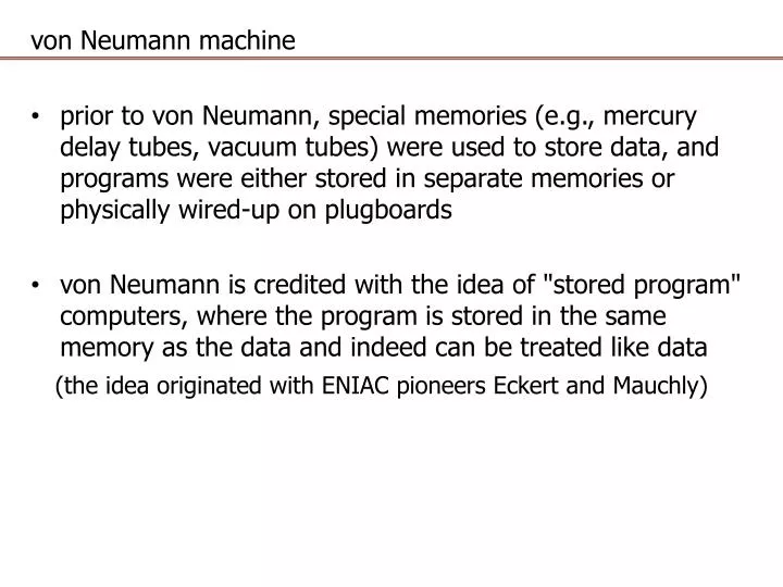
von Neumann machine prior to von Neumann, special memories (e.g., mercury delay tubes, vacuum tubes ) were used to store data, and programs were either stored in separate memories or physically wired-up on plugboards

E N D
von Neumann machine • prior to von Neumann, special memories (e.g., mercury delay tubes, vacuum tubes) were used to store data, and programs were either stored in separate memories or physically wired-up on plugboards • von Neumann is credited with the idea of "stored program" computers, where the program is stored in the same memory as the data and indeed can be treated like data (the idea originated with ENIAC pioneers Eckert and Mauchly)
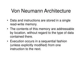
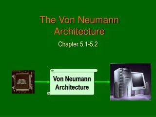
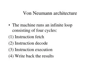
von Neumann machine characteristics • random-access, one-dimensional memory (vs. sequential memories) • stored program, no distinction between instructions and data (vs "Harvard architecture" with separate instruction and data memories) • binary, parallel by word, two's complement (vs. decimal, serial-by-digit, signed magnitude) • instruction fetch/execute cycle, branch by explicit change of PC (vs. following a link address from one instruction to the next) • three-register arithmetic -- ACC, MQ, MBR
Von Neumann Machine • memory contains series of bits grouped into addressable units NOTE: binary devices are relatively easy to build – positive feedback drives the device to one of two extreme states and keeps it there, so the decimal storage devices of some old machines were usually four binary devices for which only ten of the sixteen states were used • data is accessed in memory by naming memory addresses (like a big array)
Von Neumann Machine • addresses are consecutive binary integers (unsigned) - this is convenient for addressing arrays and sequentially stepping through a program • bit strings have no inherent data type - can be integer, character string, machine instruction, or just garbage => HARDWARE DOESN'T KNOW DATA TYPE
Von Neumann machine consider int main(){ inti; char c = 'a'; printf("%c 0x%x %d\n",c,c,c); i = c + 1; printf("%c 0x%x %d\n",i,i,i); return 0; } which prints a 0x61 97 b 0x62 98 'a' is the (ASCII-encoded) bit string '01100001'; printf() can be told to format this bit string as a character, a hexadecimal number, or a decimal number; also %s can tell printf() to use a bit string as the address of a character string
von Neumann machine note that in C programs, char parameters are passed as 32-bit words and printf() uses the lowest 8 bits for the %c format int main(){ inti = ( 'a' << 8 ) | 'b'; printf("%c 0x%x %d\n",i,i,i); i = i + 1; printf("%c 0x%x %d\n",i,i,i); return 0; } b 0x6162 24930 c 0x6163 24931 NOTE: a few old computers experimented with type fields ("tags") added to memory words to distinguish between data and instruction types the key point is that programs can be manipulated as data (e.g., think of machine code generated/modified at run time; also compiler, linker, loader)
von Neumanna machine A compiler typically type-checks all the variables it uses so that all operations are legal NOTES: • a strongly-typed language allows few, if any, implicit type conversions • in a strong and statically typed language, the compiler declares a compile-time error when types don't match (e.g., Ada, Java) • in a strong and dynamically typed language, the interpreter or other run-time system declares a run-time error when types don't match (e.g., Python) • because C is generous in using implicit conversions, it is considered weakly-typed with static (compile-time) type checking
Varieties of processors • stack machine - operands are on stack, push from memory/pop into memory • accumulator machine - one processor register, all other operands are in memory, and expressions require sequence of load/operate/store insts. • load/store machine - computational instructions operate on general registers and load/store instructions are only ones that access memory
Closer view of CPU - central processing unit data path • data registers such as ACC (accumulator) or set of general registers • address registers such as SP (stack pointer) and Xn (index registers) • ALU (arithmetic and logic unit) which executes operations • internal buses (transfer paths)
Closer view of CPU - central processing unit memory bus interface / BIU (bus interface unit) • MAR (memory address register) • MDR (memory data register) -- perhaps better called memory _buffer_ reg. control • PC (program counter) - points to next instruction (x86 calls it the IP == instruction pointer) • IR (instruction register) - holds current instruction • PSR (processor status register) - indicates results of previous operation (called condition codes or flags)
closer view of CPU - central processing unit … … to and from memory … … … Control signals to cause datapath actions are generated by logic in the control unit Move PC to MAR read memory . . .
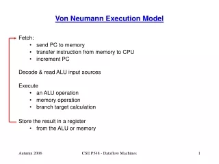
fetch-execute cycle • each instruction generates a sequence of control signals (instruction fetch is the same for each instruction) • the control signals determine the register transfers in data path • timing - how long should the control signals be active? data signals must travel from a register, across the bus, through the ALU, to a register => minimum clock cycle time • clock rate = 1 / minimum clock cycle time • performance difference over 50+ years 100 KHz ENIAC (ca. 1946) add 20 cycles = 200 microseconds = 200 * 10-6secs 3.8 GHz Pentium 4 (ca. 2006) add 1/2 cycle = 132 picoseconds = 132 * 10-12secs => 660,000 times faster cf. 1946 army jeep at 30 mph 2006 "warp" car at 19,800,000 mph
fetch-execute flowchart fetch decode +---+---------------+---------------------+---------- ... like a switch statement – decode selects one of these execution paths execute store execute load execute add ... ... +---+---------------+---------------------+---------- ... for A := B + C ; assembly code / action on computer ; load(B) ; ACC <- memory[B] register is loaded with a copy ; of the value in memory[B] add(C) ; ACC <- ACC + memory[C] value in ACC register is added with ; a copy of the value in memory[C], ; and sum is placed in ACC register store(A) ; memory[A] <- ACC memory[A] gets a copy of the value ; in ACC register
register transfers (datapath actions) for these three instructions ---fetch--- MAR PC READ IR MDR PC PC + incr decode IR ---decode--- +----------------------------+------------------------+ ---execute--- get address fetch operand execute store result load store(A) MAR addr(IP) MDR ACC _ _ _ _ _ _ _ _ WRITE load(B) MAR addr(IP) READ ACC MDR _ _ _ _ _ _ _ _ add(C) MAR addr(IP) READ ACC ACC + MDR _ _ _ _ _ _ _ _ _ +--------------------------+----------------------------+ can check for external signals (interrupts) between instructions
accumulator machine instruction set opcode address operation name machine action ------ ------- -------------- -------------- halt ---- halt stop execution div addr divide acc= acc/memory[addr] muladdr multiply acc= acc*memory[addr] sub addr subtract acc= acc-memory[addr] add addr add acc= acc+memory[addr] load addr load acc= memory[addr] store addr store memory[addr] = acc baaddr branch always pc = addr blt0 addr branch on less than if acc<0 then pc = addr ble0 addr branch on less than or equal if acc<=0 then pc = addr beq0 addr branch on equal if acc==0 then pc = addr bne0 addr branch on not equal if acc/=0 then pc = addr bge0 addr branch on greater than or equal if acc>=0 then pc = addr bgt0 addr branch on greater than if acc>0 then pc = addr print addr print display contents of memory[addr]
assembly language pseudo-ops name arg1 arg2 meaning ----- ---- ---- ------- comment text allows for comments within program end symbol defines starting address of program (should appear once, as the last line of the program) label symbol defines a symbolic address within the program word symbol value defines a symbol address and allocates a data word at that address with the given value Accumulator machine program - example 1: comment(` first example accumulator machine program ') comment(` ') comment(` data section for program -- word(label,value) ') word(a,0) word(b,3) word(c,48) word(d,9) comment(` code that implements the expression a = b + c - d; ') label(start) load(b) comment(` ACC <- memory[b] ') add(c) comment(` ACC <- ACC + memory[c] ') sub(d) comment(` ACC <- ACC - memory[d] ') store(a) comment(` memory[a] <- ACC ') halt comment(` start execution at label start ') end(start)
accumulator machine • executable is in numeric format -- example assembly (numbers are in decimal rather than binary) • the assembler has a location counter variable called "loc" that it uses in the first pass to assign addresses
accumulator machine instruction table (built into assembler) ---------------------------------------- name opcodeargsloc increment ---- ------ ---- ------------- add 40 $1 2 <- add is defined as two words sub 30 $1 2 * first word is opcode 40 load 50 $1 2 * second word is address of arg store 60 $1 2 * loc should be incremented by 2 halt 00 1 Pass 1 first pass input -- symbol table after first pass assembly statements label addr==loc ------------------- ----- --------- word(a,0) a 00 <- a is defined as location 00 word(b,3) b 01 <- b is defined as location 01 word(c,48) c 02 <- c is defined as location 02 word(d,9) d 03 <- d is defined as location 03 label(start) start 04 <- start defined as location 04 ... << no other statements define labels >> ...
accumulator machine Pass 2 second pass input "executable" after second pass ----------------- ------------------------------ (loc:) assembly language addr: machine code or data ------ ----------------- ----- -------------------- (00:) word(a,0) 00: 0 <- value in location a (01:) word(b,3) 01: 3 <- value in location b (02:) word(c,48) 02: 48 <- value in location c (03:) word(d,9) 03: 9 <- value in location d label(start) (04:) load(b) 04: 50 <- opcode for load 05: 01 <- address of b (06:) add(c) 06: 40 <- opcode for add 07: 02 <- address of c (08:) sub(d) 08: 30 <- opcode for sub 09: 03 <- address of d (10:) store(a) 10: 60 <- opcode for store 11: 00 <- address of a (12:) halt 12: 00 <- opcode for halt (13:) end(start) 13: 04 <- starting address
accumulator machine program– example 2 comment(` code that implements the loop ') comment(` sum = 0; ') comment(` for( i = 10; i > 0; i-- ){ ') comment(` sum = sum + i; ') comment(` } ') label(start) load(zero) comment(` sum = 0 ACC <- memory[zero] ') store(sum) comment(` memory[sum] <- ACC ') load(ten) comment(` i = 10 ') store(i) label(loop) load(i) comment(` branch to done if i <= 0 ') ble0(done) load(sum) comment(` sum = sum + i ') add(i) store(sum) load(i) comment(` i = i - 1 ') sub(one) store(i) ba(loop) comment(` unconditionally go back to loop ') label(done) halt )
accumulator machine program– example 2 comment(` data section for program - can be at bottom ') word(sum,0) word(i,0) word(zero,0) word(one,1) word(ten,10) comment(` start execution at label start ') end(start)