Download

1 / 47
470 likes | 490 Views
International Computer Institute, Izmir, Turkey E-R Model. Asst.Prof.Dr. İlker Kocabaş UBİ502 at http://ube.ege.edu.tr/~ikocabas/teaching/ubi502/index.html. Entity-Relationship Model. Entity Sets Relationship Sets Design Issues Mapping Constraints Keys E-R Diagram Extended E-R Features

E N D
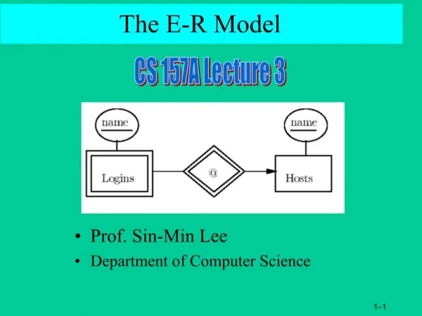
International Computer Institute, Izmir, TurkeyE-R Model Asst.Prof.Dr.İlker KocabaşUBİ502 at http://ube.ege.edu.tr/~ikocabas/teaching/ubi502/index.html
Entity-Relationship Model • Entity Sets • Relationship Sets • Design Issues • Mapping Constraints • Keys • E-R Diagram • Extended E-R Features • Weak entity sets • Specialization • Generalization • Aggregation • Design of an E-R Database Schema • Reduction of an E-R Schema to Tables
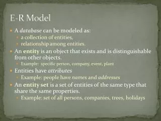
Weak Entity Sets • Assumption: entity sets always have a key • This is not always true • Examples: • Dependents covered by an employee’s insurance policy • Film crews working at a movie studio • Species within a genus • Properties • Weak entity set lacks a key • Existence of weak entities depends on existence of corresponding entities in the “identifying entity set” • i.e. the participation of the weak entity in the database is only by virtue of its relationship to the identifying entity • E.g. we’re not interested in film crews except insofar as they are associated with a movie studio (an idiosyncratic property of our enterprise)
Weak Entity Sets • Defn: An entity set that does not have a primary key • The existence of a weak entity set depends on • the existence of a identifying entityset • must relate to the identifying entity set via a total, many-to-one relationship set • Identifying relationship depicted using a double diamond • The discriminatorof a weak entity set: • the set of attributes that distinguish among all the entities of a weak entity set (also known as a partial key) • The primary key of a weak entity set: • the primary key of the strong entity set on which the weak entity set is existence dependent, plus • the weak entity set’s discriminator.
Weak Entity Sets (Cont.) • We depict a weak entity set by double rectangles. • We underline the discriminator of a weak entity set with a dashed line. • payment-number – discriminator of the payment entity set • Primary key for payment – (loan-number, payment-number)
Weak Entity Sets (Cont.) • Note: the primary key of the strong entity set is not explicitly stored with the weak entity set, since it is implicit in the identifying relationship. • If loan-number were explicitly stored, payment could be made a strong entity, but then the relationship between payment and loan would be duplicated by an implicit relationship defined by the attribute loan-number common to payment and loan
More Weak Entity Set Examples • In a university, a course is a strong entity and a course-offering can be modeled as a weak entity • The discriminator of course-offering would be semester and year • If we model course-offering as a strong entity we would model course-number as an attribute. • Then the relationship with course would be implicit in the course-number attribute
Specialization • Top-down design process • Start with few entity sets having many attributes • E.g. person entity may have attributes suitable for students, lecturers, employees, employers, etc. • we identify distinctive subgroupings within an entity set • These subgroupings become lower-level entity sets • They have attributes or participate in relationships that do not apply to the higher-level entity set • Depicted by a triangle component labeled ISA • E.g. customer “is a” person • Inheritance • a lower-level entity set inherits all the attributes and relationship participation of the higher-level entity set to which it is linked.
Generalization • A bottom-up design process • start with lots of distinct entities that share attributes • combine a number of entity sets that share the same attributes into a higher-level entity set. • Specialization and generalization are simple inversions of each other; they are represented in an E-R diagram in the same way.
Specialization and Generalization (Contd.) • Can have multiple specializations of an entity set based on different features. • E.g. permanent-employee vs. temporary-employee, in addition to officer vs. secretary vs. teller • Each particular employee would be • a member of one of permanent-employee or temporary-employee, • and also a member of one of officer, secretary, or teller • The ISA relationship also referred to as superclass - subclass relationship
Design Constraints on a Specialization/Generalization • Constraint on which entities can be members of a given lower-level entity set. • condition-defined • E.g. all customers over 65 years are members of senior-citizen entity set; senior-citizen ISA person. • user-defined • Constraint on whether or not entities may belong to more than one lower-level entity set within a single generalization. • Disjoint • an entity can belong to only one lower-level entity set • write disjoint next to the ISA triangle • Overlapping • an entity can belong to more than one lower-level entity set
Design Constraints on a Specialization/Generalization (Contd.) • Completenessconstraint • Does an entity in the higher-level entity set have to belong to at least one of the lower-level entity sets? • Total • an entity must belong to one of the lower-level entity sets • Partial • an entity need not belong to one of the lower-level entity sets
Aggregation • Consider the ternary relationship works-on • Suppose we want to record managers for tasks performed by an employee at a branch
Aggregation (Cont.) • works-on and manages represent overlapping information • Every manages relationship corresponds to a works-on relationship • some works-on relationships may not correspond to any manages relationships • we can’t discard the works-on relationship
Aggregation (Cont.) • Eliminate this redundancy via aggregation • Treat works-on relationship as an abstract entity • Allow relationships between relationships! • Abstraction of relationship into new entity • Without introducing redundancy, the following diagram represents: • An employee works on a particular job at a particular branch • An employee, branch, job combination may have an associated manager
E-R Design Principles • Faithfulness • Entities, attributes and relationships should reflect reality • Sometimes the correct approach is not obvious • E.g. course and instructor entities and teaching relationship • What are the cardinality constraints? It depends… • Avoiding Redundancy • No information should be repeated • Wastes space, leads to consistency problems • Simplicity • Some relationships may be unnecessary • E.g. student member-of student-body attends course vs student attends course • Choosing the right kind of element • The use of an attribute or entity set to represent an object • Whether a real-world concept is best expressed by an entity set or a relationship set • Choosing the right relationships • The use of a ternary relationship versus a pair of binary relationships • The use of a strong or weak entity set. • The use of specialization/generalization – contributes to modularity in the design. • The use of aggregation – can treat the aggregate entity set as a single unit without concern for the details of its internal structure.
Exercise title name Stars Movies year address ? Studios name address
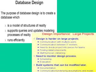
Reduction of an E-R Schema to Tables • Primary keys allow entity sets and relationship sets to be expressed uniformly as tables which represent the contents of the database. • A database which conforms to an E-R diagram can be represented by a collection of tables. • For each entity set and relationship set there is a unique table which is assigned the name of the corresponding entity set or relationship set. • Each table has a number of columns (generally corresponding to attributes), which have unique names. • Converting an E-R diagram to a table format is the basis for deriving a relational database design from an E-R diagram.
Representing Entity Sets as Tables • A strong entity set reduces to a table with the same attributes.
Composite and Multivalued Attributes • Composite attributes are flattened out by creating a separate attribute for each component attribute • E.g. given entity set customer with composite attribute name with component attributes first-name and last-name the table corresponding to the entity set has two attributesname.first-name and name.last-name • A multivalued attribute M of an entity E is represented by a separate table EM • Table EM has attributes corresponding to the primary key of E and an attribute corresponding to multivalued attribute M • E.g. Multivalued attribute dependent-names of employee is represented by a tableemployee-dependent-names( employee-id, dname) • Each value of the multivalued attribute maps to a separate row of the table EM • E.g., an employee entity with primary key John and dependents Johnson and Johndotir maps to two rows: (John, Johnson) and (John, Johndotir)
Representing Weak Entity Sets • A weak entity set becomes a table that includes a column for the primary key of the identifying strong entity set
Representing Relationship Sets as Tables • A many-to-many relationship set is represented as a table with columns for the primary keys of the two participating entity sets, and any descriptive attributes of the relationship set. • E.g.: table for relationship set borrower
Redundancy of Tables • Many-to-one and one-to-many relationship sets that are total on the many-side can be represented by adding an extra attribute to the many side, containing the primary key of the one side • E.g.: Instead of creating a table for relationship account-branch, add an attribute branch to the entity set account
Redundancy of Tables (Cont.) • For one-to-one relationship sets, either side can be chosen to act as the “many” side • That is, extra attribute can be added to either of the tables corresponding to the two entity sets • If participation is partial on the many side, replacing a table by an extra attribute in the relation corresponding to the “many” side could result in null values • The table corresponding to a relationship set linking a weak entity set to its identifying strong entity set is redundant. • E.g. The payment table already contains the information that would appear in the loan-payment table (i.e., the columns loan-number and payment-number).
Representing Specialization as Tables • Method 1: • Form a table for the higher level entity • Form a table for each lower level entity set, include primary key of higher level entity set and local attributes tabletable attributesperson name, street, city customer name, credit-ratingemployee name, salary • Drawback: getting information about, e.g., employee requires accessing two tables
Representing Specialization as Tables (Cont.) • Method 2: • Form a table for each entity set with all local and inherited attributes table table attributesperson name, street, city customer name, street, city, credit-ratingemployee name, street, city, salary • If specialization is total, table for generalized entity (person) not required to store information • Can be defined as a “view” relation containing union of specialization tables • But explicit table may still be needed for foreign key constraints • Drawback: street and city may be stored redundantly for persons who are both customers and employees
Relations Corresponding to Aggregation • To represent aggregation, create a table containing • primary key of the aggregated relationship, • the primary key of the associated entity set • Any descriptive attributes
Relations Corresponding to Aggregation (Cont.) • E.g. to represent aggregation manages between relationship works-on and entity set manager, create a tablemanages(employee-id, branch-name, title, manager-name) • Table works-on is redundant provided we are willing to store null values for attribute manager-name in table manages
The Relational Model • Structure of Relational Databases • Structure of a relation • Structure of a database • Keys • Relational Algebra • Relational operators • Example queries • Natural join
Cartesian Product • let D1, D2, …. Dn be entity sets (or domains) • The Cartesian product of D1, D2, …. Dn, writtenD1 x D2 x … x Dnis the set of n-tuples over combinations of entities • Example: if customer-name = {Jones, Smith}customer-street = {Main, North}customer-city = {Harrison} Then customer-name x customer-street x customer-city = { (Jones, Main, Harrison), (Smith, Main, Harrison), (Jones, North, Harrison), (Smith, North, Harrison) }
Structure of a Relation • a relation r is a subset of D1 x D2 x … x Dn • i.e. a set of n-tuples (a1, a2, …, an) where each ai Di • Example: if customer-name = {Jones, Smith, Curry, Lindsay}customer-street = {Main, North, Park}customer-city = {Harrison, Rye, Pittsfield}Then r = { (Jones, Main, Harrison), (Smith, North, Rye), (Curry, North, Rye), (Lindsay, Park, Pittsfield) } is a relation over customer-name x customer-street x customer-city • A relation is a set, therefore unordered (more about this later…)
Attribute Types • Each attribute of a relation has a name • Names are unique within any given relation • The set of allowed values for each attribute is called the domain of the attribute • Attribute values are (normally) required to be atomic, that is, indivisible • multivalued attribute values are not atomic (e.g. phone-number) • composite attribute values are not atomic (e.g. address) • The special value null is a member of every domain • The null value causes complications in the definition of many operations • we ignore the effect of null values for now
Relation Schema • A1, A2, …, Anare attributes • R = (A1, A2, …, An ) is a relation schema E.g. Customer-schema = (customer-name, customer-street, customer-city) • r(R) is a relation on the relation schema R E.g. customer (Customer-schema)
Relation Instance • The current values (relation instance) of a relation are specified by a table • An element t of r is called a tuple • Each tuple is represented by a row in a table attributes (or columns) customer-name customer-street customer-city Jones Smith Curry Lindsay Main North North Park Harrison Rye Rye Pittsfield tuples (or rows) customer
Relations are Unordered • Order of tuples is irrelevant (tuples may be stored in an arbitrary order) • The following two tables represent the same relation: • No significance to ordering • because both tables represent sets
Structure of a Database • A database consists of one or more relations • Information about an enterprise is broken down into its components • Each relation stores just part of the information E.g.: account : information about accountsdepositor : information about which customer owns which account customer : information about customers • Storing all information as a single relation such as bank(account-number, balance, customer-name, ..)results in • repetition of information (e.g. two customers own an account) • the need for null values (e.g. represent a customer without an account)
Superkeys • Let R be the relation schema, and let K R • K is a superkeyof R if values for K are sufficient to identify a unique tuple of each possible relation r(R) • possible = a relation r that could exist in the enterprise we are modelling. • E.g. {customer-name,customer-street} • E.g. {customer-name} • Both are superkeys of Customer, if no two customers can possibly have the same name.
Candidate Keys • K is a candidate key if: • K is a superkey • K is minimal (contains no superkeys) • {customer-name} is a candidate key for Customer • it is a superkey(assuming no two customers can have the same name) • no subset of K is a superkey.