Download
1 / 37
1.85k likes | 3.94k Views
Prius PHV. Plug-in Hybrid Vehicle. Toyota Motor Europe. [Electric Power Path]. : DC. : AC. Overview. Hybrid Vehicle Transaxle Assembly. Engine. Power Split Planetary Gear Unit. MG1. Main. Sub 1. Sub 2. MG2. HV Battery (3 packs). Motor Speed Reduction Planetary Gear Unit.

E N D
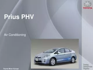
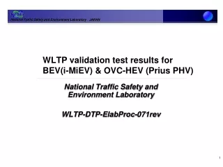
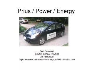
Prius PHV Plug-in Hybrid Vehicle Toyota Motor Europe
[Electric Power Path] : DC : AC Overview Hybrid Vehicle Transaxle Assembly Engine Power Split Planetary Gear Unit MG1 Main Sub 1 Sub 2 MG2 HV Battery (3 packs) Motor Speed Reduction Planetary Gear Unit Battery Charger Inverter with Converter Assembly Battery Charger Cable
Layout of main components • HV Battery Assembly • Lithium-ion Battery (DC 345.6 V) • HV Junction Block Assembly • Battery Smart Unit • DC/DC Converter for Auxiliary Battery • Charger Relay Battery Charger 2ZR-FXE Engine Auxiliary Battery (Sealed Type) Compressor with Motor Assembly Power Cable Battery Charger Inlet Power Management Control ECU (HV CPU) ECM • Inverter with Converter Assembly • Boost Converter (x 2) • Inverter • MG ECU • P410 Hybrid Transaxle • MG1 • MG2
Inverter with converter assembly High-voltage Cable for HV Battery (Main) High-voltage Cable for MG2 High-voltage Cable for MG1 High-voltage Cable for Electric A/C Compressor High-voltage Cable for HV Battery (Sub 1, 2)
Inverter with converter assembly Capacitor Inverter Terminal Cover with Interlock Switch MG ECU • IPMs • IPM for MG1 • IPM for MG2 • Boost IPM (Main) Boost IPM (Sub 1, 2) Reactor
Inverter with converter assembly Inverter with Converter Assembly IPM Boost Converter (Sub 1, 2) Inverter Battery Charger IGBT SMRs MG1 HV Battery Pack (Sub 1, 2) Inverter Current Sensors Boost Converter Current Sensor Reactor MG2 HV Battery Pack (Main) Cooler Compressor with Motor Assembly Boost Converter (Main) MG ECU S Atmospheric Pressure Sensor DC/DC Converter[Auxiliary Battery] Power Management Control ECU (HV CPU)
Safety • Before inspecting or servicing the high-voltage system, be sure to follow all safety measures CAUTION • Turn the power switch OFF, and remove the key from interior detection area for entry and start system • Disconnect the cable from auxiliary battery negative terminal • Check and wear the insulated gloves • Remove the 3 service plug grips • Wait for 10 minutes or more to discharge the high-voltage capacitor inside the inverter assembly • Measure the inverter terminal voltage (0V Check) • Insulate the disconnected high-voltage connector with insulated vinyl tape
Safety • Step 2: Disconnect negative terminal of auxiliary battery Location of Auxiliary Battery Battery Temp. Sensor Luggage Room Auxiliary Battery (Sealed-type)
Safety • Step 3: Check and wear high voltage gloves • Place the glove on its side. • Roll the opening up 2 or 3 times. • Fold the opening in half to close it. • Confirm that there are no air leaks. [Previous Procedure]
Safety • Step 4: Remove the three service plug grips Insulated Glove Keep in your pocket Service Plug Grips
Safety • Step 5: Wait 10 minutes to discharge high voltage capacitor High-voltage Capacitor Discharge 0V Elect-ricity Service plug removal 10 min.
0 V Safety • Step 6: Make sure the high-voltage capacitor terminal voltage is 0V (Tester range: 750 V or more) Plus Terminal Minus Terminal High Voltage Fuse [High-voltage Capacitor Terminal]
Safety • Step 7: Insulate the disconnected high-voltage connector with insulated vinyl tape Insulated Vinyl Tape
Li-ion cell 3.6 V HV Battery Assembly
HV Battery Assembly • Location Service Plug Grip (Sub 1) Insulated Glove Service Plug Grip (Sub 1) Service Plug Grip (Main)
HV Battery Assembly • Main components HV Battery Cooling Blowers (x 3) Battery Smart Units x 3 Charger Relay HV Junction Block Assemblies (x 3) HV Battery Cooling Blower (for DC/DC Converter) DC/DC Converter for Auxiliary Battery Front HV Battery Pack (Sub 1) Battery Packs (Main / Sub 1) HV Battery Pack (Main) Battery Pack (Sub 2) HV Battery Pack (Sub 2) Cross-section
- - - - - - - - - - - - - - - - - - - - - - - - - - - - - - - - - - - - - - - - - - - - - - - - - - - - - - - - - - - - - - - - - - - - - - - - - - - - - - - - - - - - - - - - - - - - - - - - - - - - - - - - - - - - - - - - - - - - - - - - - - - - - - - - - - - - - - - - - - - - - - - - + + + + + + + + + + + + + + + + + + + + + + + + + + + + + + + + + + + + + + + + + + + + + + + + + + + + + + + + + + + + + + + + + + + + + + + + + + + + + + + + + + + + + + + + + + + + + + + + + + + + + + + + + + + + + + + + + + + + + + + + + + + + + + + + + + + + + + + + + + + + + + + + + + + + + + + + + + + + + + + + + + + + + + + + + + + + + + + + + + + + + + + + + + + + + + + + + + + + + + + + + + + + + + + + + + + + + + + + + + + + + + + + + + + + + + + + + + + + + + + + + + + + + + + + + + + + + + + + + + + + + + + + + + + + + + + + + + + + + + + + + + + + + + + + - - - - - - - - - - - - - - - - - - - - - - - - - - - - - - - - - - - - - - - - - - - - - - - - - - - - - - - - - - - - - - - - - - - - - - - - - - - - - - - - - - - - - - - - - - - - - - - - - - - - - - - - - - - - - - - - - - - - - - - - - - - - - - - - - - - - - - - - - - - - - - - - HV Battery Assembly • Battery pack J/B (Main) J/B (Sub 1) J/B (Sub 2) SMRs SMRs SMRs HV Battery Pack (Main) [345.6 V] HV Battery Pack (Sub 2) [345.6 V] HV Battery Pack (Sub 1) [345.6 V] 1 Stack (32 Cells) Service Plug Grip (Main) Service Plug Grip (Sub 1) Service Plug Grip (Sub 2) 32 cells = 1 stack 3 stacks = 1 pack 3 packs = 1 HV battery assembly
HV Battery Assembly • HV Battery Cooling System Intake Air Duct (Sub 1) HV Battery Cooling Blower (Sub 1) Intake Air Duct (Sub 2) HV Battery Cooling Blower (Main) Intake Air Duct (Main) HV Battery Cooling Blower (Sub 2)
HV Battery Assembly • Battery Cooling System HV Battery Pack (Main) : Temp. sensor for HV battery pack (36 temp. sensors are fitted on the battery packs) HV Battery Pack (Sub 1) Front : Temp. sensor for intake air (6 sensors are located in an intake air duct) HV Battery Pack (Sub 2)
HV Battery Assembly • HV Junction Block Assembly HV Junction Block Assembly (Sub 2) HV Battery Current Sensor SMRP HV Junction Block Assembly (Sub 1) Precharge Resistor SMRB SMRG HV Junction Block Assembly (Main) NOTE: Do NOT remove SMRs on the HV junction block assembly.
HV Battery Assembly • HV Junction Block Assembly Power Management Control ECU (HV CPU) Battery Smart Unit Battery Smart Unit Battery Smart Unit Current Sensor SMRB Resistor HV Junction Block Assembly (Main) HV Junction Block Assembly (Sub 2) SMRP SMRG HV Junction Block Assembly (Sub 1) HV Battery Pack (Sub 1) HV Battery Pack (Main) HV Battery Pack (Sub 2) To Power Cable To Power Cable To Power Cable
HV Battery Assembly • HV Battery Control 80 (%) Expanded SOC usable range SOC (%) 60? (%) Time
HV Battery Assembly • HV Battery Control 80 (%) HV Battery Pack (Sub 2) HV Battery Pack (Main) SOC (%) HV Battery Pack (Sub 1) 20? (%) Time [B] Main + Sub1 [A] Main + Sub 2 Main EV Drive Mode HV Drive Mode [A] Connects Sub2 and disconnects Sub1 [B] Disconnects Sub2
Plug-in Charging System • Main components HV Battery Assembly • Battery Packs • HV Junction Block Assembly • Battery Smart Unit • Charger Relay • DC/DC Converter for Auxiliary Battery Battery Charger Charger Indicator Power Management Control ECU (HV CPU) • Battery Charger Cable • Battery Charger Connector • CCID (Charging Circuit Interrupter Device) Battery Charger Inlet
Plug-in Charging System • Battery Charger Connector Leak Detection Switch Battery Charger Inlet Power Management Control ECU (HV CPU) 1. PISW 2. CPLT 5 4 3. GND Battery Charger 4. COLD 5. HOT 2 1 3 Battery Charger Connector
Plug-in Charging System • CCID (Charging Circuit Interrupter Device) (1) (2) (3) (4) CCID
Plug-in Charging System • Battery Charging Inlet Battery Charger Inlet Battery Charger Lid (Push open-type)
Plug-in Charging System • Battery Charger 220 V AC 345.6 V DC
Plug-in Charging System • Charger Relay Charger Relay
Plug-in Charging System • Charger Relay Inverter with Converter Assembly HV Junction Block Assy (Main) Boost Converter (Main) Battery Pack (Main) SMRs Boost Converter (Sub 1, 2) HV Junction Block Assy (Sub 1) Battery Charger CHRB Battery Pack (Sub 1) SMRs CHRG HV Junction Block Assy (Sub 2) Charger Relay Power Management Control ECU (HV CPU) Battery Pack (Sub 2) SMRs
Plug-in Charging System • Battery Charger Indicator
Plug-in Charging System DC/DC Converter Inverter with Converter Assembly Boost Converter (Main) Battery Smart Unit (Main) Boost Converter (Sub 1, 2) HV Junction Block Assy (Main) Battery Pack (Main) Charger Indicator SMRs Power Management Control ECU (HV CPU) CCDI Battery Smart Unit (Sub 1) Charger Connector HV Junction Block Assy (Sub 1) Battery Pack (Sub 1) Charger Inlet SMRs MG ECU Battery Smart Unit (Sub 2) HV Junction Block Assy (Sub 2) Battery Charger Charger Relay Battery Pack (Sub 2) SMRs : Recharge Order Main > Sub1 > Sub 2 > Main > Finish
Hybrid System Operation • Operation Prius PHV ≈ Operation Prius 3 Hybrid Vehicle Transaxle Assembly Engine Power Split Planetary Gear Unit HV Battery Assembly MG1 Main Sub 1 Sub 2 MG2 Motor Speed Reduction Planetary Gear Unit Battery Charger Battery Charger Cable Inverter with Converter Assembly
Hybrid System Operation • During deceleration in EV-mode HV Battery Assembly MG1 Main Sub 1 Sub 2 MG2
Diagnosis • Data List: • 183 New parameters in the data list • DTC's: • 103 New DTC's adopted
Inspection Mode • Not using the tester OFF >>>IG-ON IG-ON >>> READY within 60 seconds Shift Position Accelerator Pedal Operation DepressTwice DepressTwice DepressTwice READY NOTICE:When operating Inspection Mode, apply the parking brake securely to prevent the vehicle moves