Download
1 / 27
270 likes | 272 Views
This article discusses the progress and plans for the T2K Target & Secondary Beamline towards a Neutrino Superbeam, including beam powers, components, and target design.

E N D
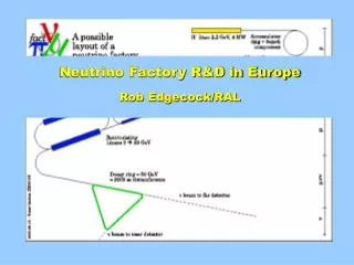
T2K Target & Secondary Beamline- progress towards a neutrino Superbeam? Chris Densham
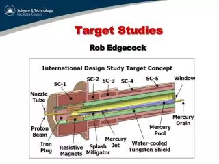
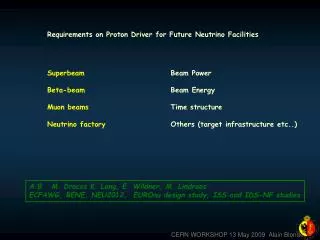
T2K: Off-Axis Neutrino Beam Super-K. q Decay Pipe Target Horns (ref.: BNL-E889 Proposal) • Quasi Monochromatic Beam • x 2~3 intense than NBB Tuned at oscillation maximum Statistics at SK (OAB 2.5 deg,1 yr,22.5 kt) ~ 2200nmtot ~ 1600nmCC ne~0.4% atnmpeak OA0° OA2° OA2.5° OA3° Neutrino energy spectrum sxF
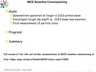
― ‘Official’ T2K Roadmap― (as quoted by Kobayashi-san 2 weeks ago at CARE) After 2010, plan depends on financial situation 3
Specified Beam Powers for T2K Secondary Beamline design – towards a Superbeam • Start-up date: 1st April 2009 (Japanese politics) • Components built for Phase I: 0.75 MW • Beam window • Baffle (collimator) • Target + 1st horn • Phase II power: 1.66 MW • Expected within 5 years • Need to start work on target + 1st horn system upgrade soon • Components built for ultimate power: 3-4 MW • Target station • Decay volume • Hadron absorber (beam dump)
T2K Secondary Beam Line Primary beam line Fast extraction 50 GeV PS ring Kamioka Target station (TS) •Target & horns in helium vessel •Helium vessel and iron shields cooled by water ‘280 m’ neutrino detector Decay Volume (DV) •94m long helium vessel cooled by water •6m thick concrete shield TS Hadron Absorber (Beam Dump) •graphite core in helium vessel BD DV
4 MW Beam Dump / Hadron Absorber Graphite Blocks Beam Displacement (max) = 8.5 mm at 4 MW 6
T2K Target Station Primary beam line Fast extraction 50 GeV PS ring Kamioka Target station (TS) •Target & horns in helium vessel •Helium vessel and iron shields cooled by water ‘280 m’ neutrino detector Decay Volume (DV) •94m long helium vessel cooled by water •6m thick concrete shield TS Hadron Absorber (Beam Dump) •graphite core in helium vessel BD DV
T2K Target area Inner concrete shields Inner iron shields Support structure = Helium vessel (being constructed by Mitsui Ship. Co.) 3rd horns 2nd horns Baffle Target and 1st horns Beam window
Specification of Phase 1 Target Design • Graphite rod, 900 mm (2 interaction lengths) long, 26 mm (c.2σ) diameter • c.20 kW (3%) of 750 kW Beam Power dissipated in target as heat • Helium cooled (i)to avoid shock waves from liquid coolants e.g. water and (ii)to allow higher operating temperature • Target rod completely encased in titanium to prevent oxidation of the graphite • Helium cools both upstream and downstream titanium window first before cooling the target due to Ti-6Al-4V material temperature limits • Pressure drop in the system should be kept to a minimum due to high flow rate required (max. 0.8 bar available for target at required flow rate of 32 g/s (30% safety margin)) • Target to be uniformly cooled (but kept above 400°C to reduce radiation damage) • It should be possible to remotely change the target in the first horn • Start-up date: 1st April 2009
Inlet manifold Target Design: Helium cooling path Outlet manifold Graphite to titanium diffusion bond Flow turns 180° at downstream window Upstream Window Graphite-to-graphite bond
Diffusion Bond + Graphite-Graphite bonding test IG43 Graphite diffusion bonded into Ti-6Al-4V titanium, Special Techniques Group at UKAEA Culham Graphite-Graphite bonding Graphite transfer to Aluminium Aluminium intermediate layer, bonding temperature 550ºC Soft aluminium layer reduces residual thermal stresses in the graphite
Steady state target temperature 30 GeV, 0.4735Hz, 750 kW beam Radiation damaged graphite assumed (thermal conductivity 20 [W/m.K] at 1000K- approx 4 times lower than new graphite) Maximum temperature = 736˚C
Helium cooling velocity streamlines Maximum velocity = 398 m/s Pressures (gauge) Pressure drop = 0.792 bar
Prototype Target Integration with 1st Magnetic Horn – August 2008
Target installed within 1st magnetic horn
Pulsed beam induced thermal stress waves in target graphite Max. Von Mises Stress = 7 MPa - cf graphite strength ~37 MPa – should be OK Spill width ~5ms 8 bunches/spill Rep. rate: 0.47 Hz Bunch spacing: ~600(300) ns Bunch length: 58ns (Full width)
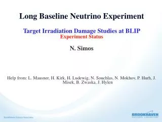
Radiation Damage in IG43 Graphite - data from Nick Simos, BNL 200 MeV proton fluence ~10^21 p/cm2 c. 1 year operation in T2K (phase 1, 750 kW) We don’t expect targets to last long! Targets can be changed within magnetic horn
Target Remote Replacement Commissioning (Nov 2008) 3 1 Installation of manipulators into hot cell Disconnecting target from horn 2 4 Offering up target replacementsystem to magnetic horn Withdrawing target from horn
Options for Neutrino Superbeams • Static target difficult beyond 1 MW beam power – problems include: • Power dissipation • Thermal stress • Radiation damage • High helium flow rate, large pressure drops or high temperatures • Expect to replace target increasingly often as beam power increases • Is it possible to combine a moving target with a magnetic horn? • New target technology may be necessary above c. 1 MW beam power
Liquid mercury jets for neutrino facilities • In principle, the problem of pulsed beam interactions with a mercury target may be solved for an open jet injected into a high-field (c.20 T) solenoid • However, many difficult engineering, materials and radiochemistry issues remain to be solved • What candidates are there for a neutrino Superbeam target, e.g. T2HK (T2K Phase 2) or at the SPL at CERN?
EUROnu proposal for CERN SPL Superbeam forsees mercury jet ( a la MERIT)… But…
A flowing powder target for a Superbeam or Neutrino Factory? See Otto Caretta’s talk Helium Powder hopper Helium Magnetic horn beam Beam window
Summary:Targets for a Neutrino Superbeam • Yield ~ target production & capture efficiency × reliability • Target efficiency much simulated/optimised, however system reliability is generally unknown • Graphite targets achievable for deposited powers up to ≈ 30 kW for multi-GeV proton beams • Limits of solid target technology not yet demonstrated • Important to distinguish between beam power (750 kW for T2K) with beam power deposited in target (20 kW for T2K) • Open liquid metal jets may be feasible for a future neutrino factory or muon collider, but not necessarily for a Superbeam • New ideas probably required for Superbeam targets e.g. different materials (Be?), flowing powders?