Download
1 / 17
170 likes | 314 Views
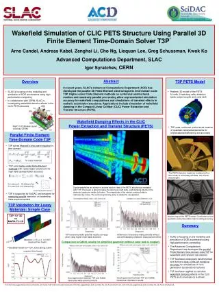
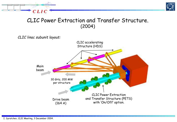
CLIC Power Extraction and Transfer Structure. (2004). CLIC linac subunit layout:. CLIC accelerating Structure (HDS). Main beam. 30 GHz, 200 MW per structure. CLIC Power Extraction and Transfer Structure (PETS) with ‘On/Off’ option. Drive beam (164 A). INTRODUCTION.

E N D
CLIC Power Extraction and Transfer Structure. (2004) CLIC linac subunit layout: CLIC accelerating Structure (HDS) Main beam 30 GHz, 200 MW per structure CLIC Power Extraction and Transfer Structure (PETS) with ‘On/Off’ option. Drive beam (164 A)
INTRODUCTION Mission: PETS should generate 800 MW, 42 ns, 30 GHz RF pulses (8 bunches spacing HDS design ). Following present CLIC main linac layout (1 PETS x 4 HDS), the PETS active length should not exceed 0.7m. PETS aperture: For the given length and RF power of the PETS, beam current scales as: and transverse wake amplitude: Constraints: #1. Drive beam accelerator length/cost scales inverse proportionally with the drive beam current. #2. Combining rings. In general higher energies require larger rings. #3. PETS reliability. One should not accept a design, when electric surface fields in PETS exceed values of that in a main linac. #4. Transverse wake in a PETS should be within acceptable level. As a compromise, PETS apertures from 20 mm to 25 mm were chosen for detailed study. Circularly symmetric structures P=800 MW L=0.7 m Drive beam energy, GeV Drive beam current, A Beam aperture, mm Beam aperture, mm HDS level E surf. , MeV/m Transverse wake, n/s Beam aperture, mm Beam aperture, mm
Phase advance and aperture PETS longitudinal impedance (by GDFIDL) 2.2 GeV 25 mm “66 GHz” check 2.7 GeV Drive beam current, A 22.5 mm V/pC/m P=800 MW L=0.7 m 3.66 GeV 20.0 mm Frequency, GHz Phase/cell degrees PETS parameters: F= 29.9855 GHz Aperture = 22.5 mm R/Q = 320.2 Ohm/m Beta = 0.798 C /cell = 1400 I Drive beam = 164 A RF power = 800 MW Active length = 0.7 m Damping slots: 8 x 2 mm 20.0 mm W, normalized 22.5 mm 25 mm PETS Phase/cell degrees The higher phase advance, the less HOM damping.
CLIC PETS in general PETS machining prototype Finally adopted PETS is represented by 22.5 mm diameter circular waveguide with shallow (~1.3 mm deep) sinus-type corrugations with 1400 phase advance per period (3.8885 mm). Eight HOM damping slots are placed symmetrically around the circumference splitting the whole structure into 8 identical pieces. To simplify the fabrication, the active profile of each of 8 racks was chosen to be flat The damping slot width (2 mm) and slot’s rounding radii (0.8 mm) provided quasi-constant surface electric field distribution. This technology is very similar to that was chosen for HDS accelerating structure. PETS geometry provides certain margins towards active length and RF power to be produced without affecting beam stability along the decelerator. PETS architecture 854 70 23 61 700 PETS Power Extractor (PPE) at 800 MW E max = 135 MV/m H max =0.22MA/m PETS regular part Matching section
Individual RF sources Transverse modes damping in PETS The transverse HOM mode in PETS to taken care of has a frequency and group velocity practically identical to the decelerating one. The only way do damp it is to use its symmetry properties. Damping mechanism in PETS can be explained as a coherent radiation of many RF sources represented by the individual period of corrugation into the infinite radial slot. The angle of radiation here depends on the phase advance and distance between them. The higher the phase advance, the smaller the angle and less the damping. In any case radiation (damping) is strongest when phase advance and period are matched. For the practical reason the infinite slot is replaced by the brad-band RF matched load: Transverse wake spectra (GDFIDL) Transverse wake amplitude (GDFIDL) Un-damped Un-damped Damped V/A/mm/m Wt, V/pC/m/mm Damped Distance, m Frequency, GHz
Transverse modes damping in PETS. HFSS versus GDFIDL. Two modes time domain approximation Z0=5.857 Power extraction Bunch Z0 F, GHz Q k, V/pC/mm/m M0 32.90 10000 0.4 F, GHz Q k, V/pC/mm/m M1 29.55 8.9(52) 0.27 M2 34.20 9.5(56) 0.12 =0.87 Un-damped =1.77 mm Damped =1.77 mm Damped =0.88 mm
Practically no effect on the beam transport of the transverse HOM can be observed now! PLACET simulations (Daniel) Beam jitter amplification Transverse modes: M1 M2 Kt, V/pC/m/mm 0.904 0.473 F, GHz 27.844 34.915 Beta 0.876 C 0.646 C Q loaded (HFSS) 40 38
RF power extraction. Adiabatic matching section Reflection regular cells Matching section S12TM02 S11TM01 Power S11TM01 S11TM02 Transmition 15 matching cells Number of matching cells S12TM02 PETS is a very over-moded RF system. Any geometrical perturbation can provoke coupling of the decelerating mode to the number of HOMs. In order to extract RF power into the smooth waveguide efficiently, a long adiabatic section is needed. A number of gradually reduced corrugations (periods) was optimised to bring the reflection and mode conversion to better than – 40 Db. Total length of matching section is 58 mm (15 periods). Number of regular cells
PETS 30 GHz 8 cannel quasi-optical RF power extractor HFSS simulations Low power prototype Backward Losses, dB Forward 20 mm Frequency, GHz -2% level Power extracted No Ohmic losses Emax: 88 MV/m at 800 MW Frequency, GHz
Average expected Average extracted Power extracted Channel number PETS 30 GHz 8 cannel quasi-optical RF power extractor (continued) Prototype low power RF measurements Power budget per channel: E01 mode launcher Matching transformer Reflection S11 Efficiency: 97.0 % S1-2...5 S1-6...9
Full geometry HFSS simulation S11(01) Power Extractor Isolation, dB Output Matching section S11(02) Regular PETS (6 cells) S12(01) S12(02) Frequency, GHz Input Matching section R12.75 R13.0 Extractor resonances Extraction, dB Matching ring (S 3.0mm) Frequency, GHz
L=0.5 m L=0.7 m CLIC PETS FZF, GHz L=0.9 m Vgroup/C CLIC PETS ON/OFF principle of operation Ranking 1 (TRC report) Few examples: 1. Length – 0.7 m, - 0.798 (CLIC PETS) For constant impedance structure, the RF power distribution along the structure can be expressed as: If we need to avoid power production at the end of the structure, than the detuning should be sufficient (without losses) if: Where FDis a new detuned synchronous frequency, L – length of the structure and - group velocity. For CLIC PETS FD= 31.69 GHz: Output power First Zero Frequency (FZF) Detuned frequency, GHz 2. FZF versus group velocity and structure length “ON” Power “OFF” Distance, m
CLIC PETS ON/OFF mechanism description Ideally, by insertion of 4 (1.6 mm thick) wedges through the damping slots, sufficient PETS synchronous frequency detuning can be achieved: PETS parameters evolution during wedges movement. “ON” “OFF” Vgroup/C R/Q, Ohm The need to have a technological (~0.2 mm) slit between the wedge and damping slot unfortunately forces the radiation of generated RF power. This potentially can destroy the RF loads which are not designed for the high power use. The solution is to introduce another slot along the edge of the wedge. For that we pay by certain field enhancement in a technological slit when the wedge passes its intermediate position. Wedges position, mm Wedges position, mm Esurf., V/mx1W Q-factor Straight wedge Slotted wedge Field enhancement inside the slit Ohmic value Wedges position, mm Wedges position, mm Radiation Qext=3x10⁶ Qext=105
CLIC PETS ON/OFF mechanism description (continued) Damping animation FZF Frequency, GHz Wedges inserted Vgroup/C Surface field PETS aperture Amplitude, norm. The “ON/OFF” operation can be performed with the proposed method. The FZF point is established at a radial position of the wedge of 12.0 mm. If “variable” attenuation option is required, the danger of undesired field enhancement in a technological slit does appear. Power Wedges position, mm
Hans (CLIC meeting, 20.02.04) CLIC PETS variable attenuator option. Draft. Corrugated slotted wedge Not very much-“OFF” position “OFF” position FZF Surface field Frequency, GHz Amplitude, norm. Esurf., V/mx1W Power Wedges position, mm Vgroup/C Wedges position, mm
Structure symmetry radial distortion To simplify the geometry for HFSS, the two adjusted racks were moved by 0.5 mm in radial direction(see picture). V. Pointing density EZ E-field 900 0.5 mm 0.5 mm Phase, degree E EZ Amplitude Ex10 External Q-factor: 4.8x10⁴ Cooper Q-factor: 1.2x10⁴ The imperfection in radial positioning of the single rack (within acceptable tolerances) does not create problems neither with power damping, nor with any transverse action on the beam.
Ongoing activity #1. Structure The technical drawings of 40 cm PETS full scale prototype are under preparation. The brazed version of extractor is on a waiting list. #2. ON/OF mechanism RF design of the variable option to be finalized (incl. GDFIDL runs). Future studies #1. Structure The use of damping slot for monitoring of the beam position inside PETS. #2. ON/OF mechanism Mechanical design for the fast switching should be developed.