Download
1 / 69
690 likes | 808 Views
ECE544: Communication Networks-II, Spring 2007. D. Raychaudhuri Lecture 5. Includes teaching materials from L. Peterson. Today’s Lecture. Routing metrics Scalable IP routing IPv6 Inter-domain routing (BGP). Routing Metrics. Metric choices. Static metrics (e.g., hop count)

E N D
ECE544: Communication Networks-II, Spring 2007 D. Raychaudhuri Lecture 5 Includes teaching materials from L. Peterson
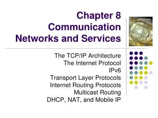
Today’s Lecture • Routing metrics • Scalable IP routing • IPv6 • Inter-domain routing (BGP)
Metric choices • Static metrics (e.g., hop count) • good only if links are homogeneous • not the case in the Internet • Static metrics do not take into account: • link delay • link capacity • link load (hard to measure)
Original ARPANET metric • Cost proportional to queue size • instantaneous queue length as delay estimator • Problems: • did not take into account link speed • poor indicator of expected delay due to rapid fluctuations • delay may be longer even if queue size is small due to contention for other resources
New metric • Delay = (depart time - arrival time) + transmission time + link propagation delay • (depart time - arrival time) captures queuing • transmission time captures link capacity • link propagation delay captures the physical length of the link • Measurements averaged over 10 seconds • Update sent if difference > threshold, or every 50 seconds
Performance of new metric • Works well for light to moderate load • static values dominate • Oscillates under heavy load • queuing dominates • Reason: there is no correlation between original and new values of delay after re-routing!
Specific problems • Range is too wide • 9.6 Kbps highly loaded link can appear 127 times costlier than 56 Kbps lightly loaded link • can make a 127-hop path look better than 1-hop • No limit in reported delay variation • All nodes calculate routes simultaneously • triggered by link update
Consequences • Low network utilization (50% in example) • Congestion can spread elsewhere • Routes could oscillate between short and long paths • Large swings lead to frequent route updates • more messages • frequent SPT re-calculation
Revised link metric Better metric: packet delay = f(queueing, transmission, propagation). When lightly loaded, transmission and propagation are good predictors When heavily loaded queueing delay is dominant and so transmission and propagation are bad predictors
Routing metric v.s. link utilization 225 New metric (routing units) 9.6 satellite 140 90 9.6 terrestrial 75 56 satellite 60 56 terrestrial 30 0 25% 50% 75% 100% Utilization
Observations • Cost of highly loaded link never more than 3*cost when idle • Most expensive link is 7 * least expensive link • High-speed satellite link is more attractive than low-speed terrestrial link
Routing dynamics Utilization Metric map 1.0 Bounded oscillation 0.75 0.5 Network response 0.25 0 0.5 1.0 1.5 2.0 2.5 3.0 3.5 4.0 Link reported cost
Routing dynamics Utilization Metric map 1.0 0.75 Easing in a new link 0.5 Network response 0.25 0 0.5 1.0 1.5 2.0 2.5 3.0 3.5 4.0 Reported cost
How to Make Routing Scale • Flat versus Hierarchical Addresses • Inefficient use of Hierarchical Address Space • class C with 2 hosts (2/255 = 0.78% efficient) • class B with 256 hosts (256/65535 = 0.39% efficient) • Still Too Many Networks • routing tables do not scale • route propagation protocols do not scale
NSFNET backbone Stanford ISU BARRNET MidNet … regional regional Westnet regional Berkeley P ARC UNL KU UNM NCAR UA Internet Structure Recent Past
Large corporation “ ” Consumer ISP Peering point Backbone service provider Peering point Consumer ” ISP “ “ Consumer ISP ” Large corporation Small corporation Internet Structure Today
Network number Host number Class B address 111111111111111111111111 00000000 Subnet mask (255.255.255.0) Network number Subnet ID Host ID Subnetted address Subnetting • Add another level to address/routing hierarchy: subnet • Subnet masks define variable partition of host part • Subnets visible only within site
Subnet mask: 255.255.255.128 Subnet number: 128.96.34.0 128.96.34.15 128.96.34.1 H1 R1 Subnet mask: 255.255.255.128 128.96.34.130 Subnet number: 128.96.34.128 128.96.34.139 128.96.34.129 H2 R2 H3 128.96.33.1 128.96.33.14 Subnet mask: 255.255.255.0 Subnet number: 128.96.33.0 Subnet Example Forwarding table at router R1 Subnet Number Subnet Mask Next Hop 128.96.34.0 255.255.255.128 interface 0 128.96.34.128 255.255.255.128 interface 1 128.96.33.0 255.255.255.0 R2
Supernetting (CIDR) • Assign block of contiguous network numbers to nearby networks • Called CIDR: Classless Inter-Domain Routing • Protocol uses a (length, value) pair length = # of bits in network prefix • Use CIDR bit mask to identify block size • All routers must understand CIDR addressing • Routers can aggregate routes with a single advertisement -> use longest prefix match
Supernetting (CIDR) • Routers can aggregate routes with a single advertisement -> use longest prefix match • Hex/length notation for CIDR address: • C4.50.0.0/12 denotes a netmask with 12 leading 1 bits, i.e. FF.F0.0.0 • Routing table uses “longest prefix match” • 171.69 (16 bit prefix) = port #1 • 171.69.10 (24 bit prefix) = port #2 • then DA=171.69.10.5 matches port #1 • and DA = 171.69.20.3 matches port#2
Route Aggregation with CIDR Corporation X (11000000000001000001) Border gateway Regional network (advertises path to 11000000000001) Corporation Y (11000000000001000000) Chapter 4, Figure 26
IP Version 6 • Features • 128-bit addresses (classless) • multicast • real-time service • authentication and security • autoconfiguration • end-to-end fragmentation • protocol extensions • Header • 40-byte “base” header • extension headers (fixed order, mostly fixed length) • fragmentation • source routing • authentication and security • other options
IPv6 Technology Scope IP Service IPv4 Solution IPv6 Solution 32-bit, Network Address Translation 128-bit, Multiple Scopes Addressing Range Serverless, Reconfiguration, DHCP Autoconfiguration DHCP Security IPSec IPSec Mandated,works End-to-End Mobile IPwith Direct Routing Mobility Mobile IP Differentiated Service, Integrated Service Differentiated Service, Integrated Service Quality-of-Service IP Multicast IGMP/PIM/Multicast BGP MLD/PIM/Multicast BGP,Scope Identifier
IPv4 & IPv6 Header Comparison IPv6 Header IPv4 Header - field’s name kept from IPv4 to IPv6 - fields not kept in IPv6 - Name & position changed in IPv6 - New field in IPv6 Legend
IPv6 Addressing • IPv6 Addressing rules are covered by multiples RFC’s • Architecture defined by RFC 2373 • Address Types are : • Unicast : One to One (Global, Link local, Site local, Compatible) • Anycast : One to Nearest (Allocated from Unicast) • Multicast : One to Many • Reserved • A single interface may be assigned multiple IPv6 addresses of any type (unicast, anycast, multicast) • No Broadcast Address -> Use Multicast
IPv6 Address Representation • 16-bit fields in case insensitive colon hexadecimal representation • 2031:0000:130F:0000:0000:09C0:876A:130B • Leading zeros in a field are optional: • 2031:0:130F:0:0:9C0:876A:130B • Successive fields of 0 represented as ::, but only once in an address: • 2031:0:130F::9C0:876A:130B • 2031::130F::9C0:876A:130B • 0:0:0:0:0:0:0:1 => ::1 • 0:0:0:0:0:0:0:0 => :: • IPv4-compatible address representation • 0:0:0:0:0:0:192.168.30.1 = ::192.168.30.1 = ::C0A8:1E01
IPv6 Addressing • Prefix Format (PF) Allocation • PF = 0000 0000 : Reserved • PF = 001 : Aggregatable Global Unicast Address • PF = 1111 1110 10 : Link Local Use Addresses (FE80::/10) • PF = 1111 1110 11 : Site Local Use Addresses (FEC)::/10) • PF = 1111 1111 : Multicast Addresses (FF00::/8) • Other values are currently Unassigned (approx. 7/8th of total) • All Prefix Formats have to support EUI-64 bits Interface ID setting • But Multicast
Aggregatable Global Unicast Addresses Provider Site Host • Aggregatable Global Unicast addresses are: • Addresses for generic use of IPv6 • Structured as a hierarchy to keep the aggregation • See draft-ietf-ipngwg-addr-arch-v3-07 3 45 bits 16 bits 64 bits Global Routing Prefix SLA Interface ID 001
Address Allocation /48 /64 /23 /32 • The allocation process is under reviewed by the Registries: • IANA allocates 2001::/16 to registries • Each registry gets a /23 prefix from IANA • Formely, all ISP were getting a /35 • With the new proposal, Registry allocates a /36 (immediate allocation) or /32 (initial allocation) prefix to an IPv6 ISP • Policy is that an ISP allocates a /48 prefix to each end customer • ftp://ftp.cs.duke.edu/pub/narten/ietf/global-ipv6-assign-2002-04-25.txt 2001 0410 Interface ID Registry ISP prefix Site prefix Bootstrap process - RFC2450 LAN prefix
ISP 2001:0410::/32 Customerno 2 Customerno 1 IPv6 Internet 2001::/16 Hierarchical Addressing & Aggregation Only announces the /32 prefix • Larger address space enables: • Aggregation of prefixes announced in the global routing table. • Efficient and scalable routing. 2001:0410:0001:/48 2001:0410:0002:/48
Link-Local & Site-Local Unicast Addresses • Link-local addresses for use during auto-configuration and when no routers are present: • Site-local addresses for independence from Global Reachability, similar to IPv4 private address space 1111111010 0 interface ID 1111111011 0 SLA* interface ID
Multicast Addresses (RFC 2375) • low-order flag indicates permanent / transient group; three other flags reserved • scope field: 1 - node local • 2 - link-local • 5 - site-local • 8 - organization-local • B - community-local • E - global • (all other values reserved) flags scope group ID 11111111 8 4 4 112 bits
80 bits 16 bits 32 bits 0000……………………………0000 0000 IPv4 Address IPv6 Addresses with Embedded IPv4 Addresses 80 bits 16 bits 32 bits 0000……………………………0000 FFFF IPv4 Address IPv4 mapped IPv6 address more on IPv6 Addressing
IPv6 Addressing Examples LAN: 3ffe:b00:c18:1::/64 Ethernet0 interface Ethernet0 ipv6 address 2001:410:213:1::/64 eui-64 MAC address: 0060.3e47.1530 router# show ipv6 interface Ethernet0 Ethernet0 is up, line protocol is up IPv6 is enabled, link-local address is FE80::260:3EFF:FE47:1530 Global unicast address(es): 2001:410:213:1:260:3EFF:FE47:1530, subnet is 2001:410:213:1::/64 Joined group address(es): FF02::1:FF47:1530 FF02::1 FF02::2 MTU is 1500 bytes
BGP-4: Border Gateway Protocol • AS (Autonomous System) Types • stub AS: has a single connection to one other AS • carries local traffic only • multihomed AS: has connections to more than one AS • refuses to carry transit traffic • transit AS: has connections to more than one AS • carries both transit and local traffic • Each AS has: • one or more border routers • one BGP speaker that advertises: • local networks • other reachable networks (transit AS only) • gives path information
Example 1 2 IGP 2.1 2.2 IGP EGP 1.1 2.2.1 1.2 EGP EGP EGP 3 4.2 4.1 IGP EGP 4 IGP 5 3.2 3.1 IGP 5.2 5.1
1 2 2.1 2.2 1.1 2.2.1 1.2 3 3.2 3.1 Path Suboptimality 3 hop red path vs 2 hop green path
Choices • Link state or distance vector? • no universal metric - policy decisions • Problems with distance-vector: • Bellman-Ford algorithm may not converge • Problems with link state: • metric used by routers not the same - loops • LS database too large - entire Internet • may expose policies to other AS’s
Solution: Path Vectors • Each routing update carries the entire path • Loops are detected as follows: • when AS gets route check if AS already in path • if yes, reject route • if no, add self and advertise route further • Advantage: • metrics are local - AS chooses path, protocol ensures no loops
Problems • Routing table size • need an entry for all paths to all networks • Required memory= O(N + M*A) * K) • N: number of networks • M: mean AS distance • A: number of AS’s • K: number of BGP peers • Problem reduced with CIDR
128.96 Customer P 192.4.153 (AS 4) Regional provider A (AS 2) Customer Q 192.4.32 (AS 5) 192.4.3 Backbone network (AS 1) Customer R 192.12.69 (AS 6) Regional provider B (AS 3) Customer S 192.4.54 (AS 7) 192.4.23 BGP Example • Speaker for AS2 advertises reachability to P and Q • network 128.96, 192.4.153, 192.4.32, and 192.4.3, can be reached directly from AS2 • Speaker for backbone advertises • networks 128.96, 192.4.153, 192.4.32, and 192.4.3 can be reached along the path (AS1, AS2). • Speaker can cancel previously advertised paths