Download
1 / 17
210 likes | 467 Views
The Autonomous navigation Robot. By: 1- Aws Al- Nabulsi 2- Ibrahim Wahbeh 3- Odai Abdallah Supervised by: Dr. Kamel Saleh. Overview. The main idea of the project is to create an open source hardware and software robotic platform that can be easily adapted to do several tasks.

E N D
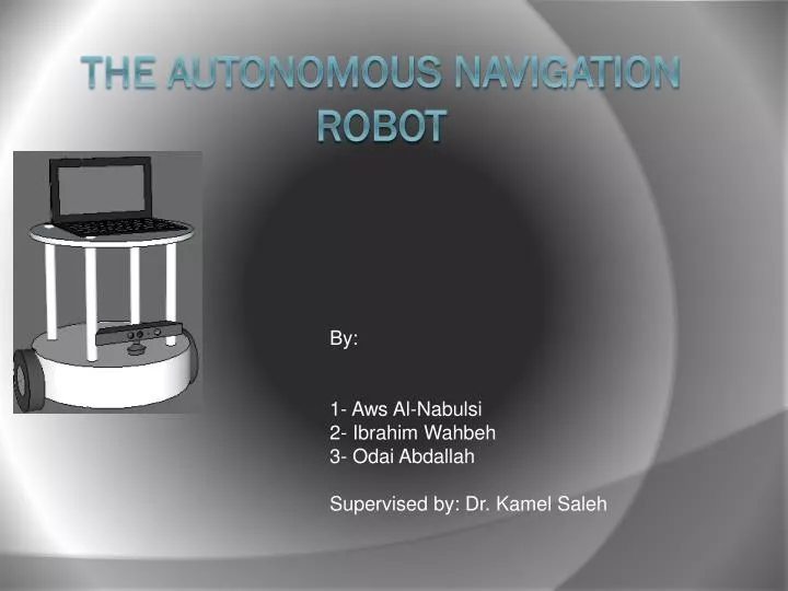
The Autonomous navigation Robot By: 1- Aws Al-Nabulsi 2- Ibrahim Wahbeh 3- OdaiAbdallah Supervised by: Dr. KamelSaleh
Overview • The main idea of the project is to create an open source hardware and software robotic platform that can be easily adapted to do several tasks. • Features of this platform: • Map construction • Localization • Path planning and obstacle avoidance • speech and object recognition
Map Construction and path planning • Estimated position (X1,Y1) • Target position (X2,Y2) • Optimum path • Move
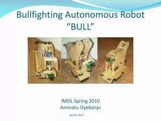
Hardware Design Body Design showing the various parts of the robot 1) Mother Board 2) Kinect sensor 3) Base 4) Wheels
The Base Controller The Base controller contains: 1)Microcontroller 2)Drive Circuit 3)Two Stepper motors 4)Battery
Choosing the motors • Torque calculations: The following formulas were used to determine the required torque T = F friction *R F friction = µ * m * g the estimated parameters for the robot are: R= 6 cm , µ = 0.35 , m= 7 kg , g=9.81 m/S2 Substituting these parameters into the equations, We get a required torque of T = 7.3545 Kg-cm per motor.
Motors used: • Two steper motors • SpecificationsSize: Nema 23 Phase: 2 PhaseStep Angle: 1.8 DegreesVoltage: 70V MaxRated Current: 2.8AInductance: 4.7mHDual ShaftBipolar 4 Wire
Drive circuit A dual H-bridge with a maximum total current of 4 A will be used to drive the motors
The arduino microcontroller • Main tasks: • send/receive data. • Odometry calculations. • Motor commands.
Kinect sensor • Features of the kinect: • RGB image • IR image • Depth map • Skeleton and object tracking
odometry calculations The term odometry means the robot coordinates in x, y and theta. And the velocity v of the robot ∆ Distance= ∆ encoder pulses * Distance per pulse ϴ Right distance = previous right distance + ∆ right distance. Left distance = previous left distance + ∆ left distance. ∆ X = ∆ distance * cos (ϴ). ∆ Y = ∆ distance * sin (ϴ). X= previous x + ∆ x. Y= previous y + ∆ y. Now to calculate the heading (ϴ): ∆ ϴ = (∆ right distance - ∆ left distance) / b. Where b is the distance between the wheels. And ϴ = previous ϴ + ∆ ϴ.
Translating the desired linear and angular velocities into motor commands: VR = V + (b * W)/2 VL = V – (b* W)/2
Thank you for your attention Questions?