Download
1 / 19
190 likes | 331 Views
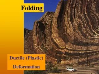
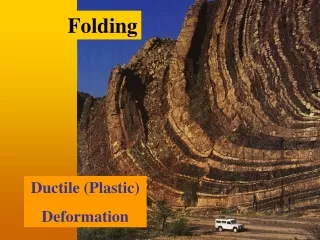
Understanding of the limiting condition for ductile components. Andrew Wasylyk. UNTF 2011. plastic zone . Plastic zone. Fracture process area. Defining Limiting Condition. Ductile components. Primary pipe work is fabricated from Grade 304 stainless steel Typical yield stress 250MPa

E N D
Understanding of the limiting condition for ductile components Andrew Wasylyk UNTF 2011
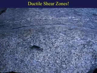
plastic zone Plastic zone Fracture process area Defining Limiting Condition
Ductile components • Primary pipe work is fabricated from Grade 304 stainless steel • Typical yield stress250MPa • Typical ductility60 - 70%
Aim Define cases under which structural integrity of ductile components may be solely assessed on plastic collapse criteria, whilst maintaining the integrity of the plant Fracture above limit load From SPECIMEN to STRUCTURE Size effect!
Defining Fracture • J-integral • Conventional methodology to define critical crack tip stress field • Validity limits • Dependence on global plasticity
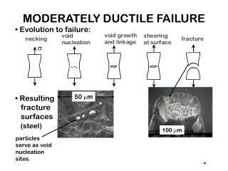
Ductile Fracture • Local Approach • Rice & Tracey local approach • Defined for ductile behaviour, growth of a void to a critical void volume fraction. • Proportional to stress, strain and triaxiality ahead of the crack tip • Will account for constraint effects.
Experiments Fracture Toughness Specimens: • a/W=0.55 • Unloading compliance methodology • Crack propagation proportional to elastic unload • Global J proportional to area under the load displacement curve • Tracking of plasticity development using Digital Image Correlation Aim • Analyse fracture under a range of Plasticity conditions • Compare methodologies defining fracture under large plasticity conditions
15mmCT 25mmCT 10mmCT
Finite Element Analysis • Boundary Layer analysis • 3D Compact Tension
Local Approach Rice and Tracey Ductile criterion Void growth in triaxial stress field Generalised form based on a range of shape factors
Conclusion Fracture behaviour of small scale specimens can be defined using a modified Rice and Tracey approach Small scale specimen can be used to define fracture behaviour without over-conservatism Plasticity is self similar in all specimens
Any Questions? Thank You for Your attention!
Image Correlation • Optical tracking of local displacement of features on the surface of the specimen • Surface preparation: • 25mm CT: White paint coating with random black speckles • 15mmCT & 10mmCT: Oxalic Acid electro-etching, I=6V,t=12min
Fracture above limit load Region III: J-Q Local Approach Energy Dissipation Region II: EPFM Region I: LEFM