Download
1 / 27
270 likes | 453 Views
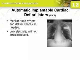
Cyber-Physical Modeling of Implantable Cardiac Medical Devices Zhihao Jiang , Miroslav Pajic and Rahul Mangharam PROCEEDINGS OF THE IEEE Presented by Yishuang Geng. Background: cardiac rhythm management devices such as pacemakers and

E N D
Cyber-Physical Modeling of Implantable Cardiac Medical Devices Zhihao Jiang, MiroslavPajicand Rahul Mangharam PROCEEDINGS OF THE IEEE Presented by Yishuang Geng
Background: cardiac rhythm management devices such as pacemakers and ICD have grown in complexity and now have more than 80,000 to 100,000 lines of code 1996 - 10% of all medical device recalls were caused by software-related issues 2006 - 21% of recalls are made up by software errors in medical devices 2010 - 23 recalls of defective devices, all of which are categorized as Class I, meaning there is a “reasonable probability that use of these products will cause serious adverse health consequences or death.” There is currently no standard for testing, validating and verifying the software for implantable medical devices
Background: Features of software embedded in medical devices: Long life span Safety-critical Challenges of software embedded in medical devices: Closed-loop context: Current evaluation of devices is open loop and is unable to ensure the device never drives the patient into an unsafe state Patient models: There is a scarcity of patient models and clinically-relevant simulators for device design. High fidelity models of interaction between the patient and device are needed to evaluate the safety and efficacy of device operation Adaptive patient-specific algorithms: The therapy offered by the device must adapt to the environment and specific patient’s condition
The FDA and Medical Device Software • United States Food and Drug Administration (FDA) is the primary • regulatory authority responsible for assuring the safety, efficacy • and security of patients using medical devices • The history of the FDA is a reactionary one, where each stage of • evolution was in response to a major health-care tragedy • Therac-25: • Overconfidence in software --- pass the test • Confusing reliability with safety --- reliable doesn’t means safe • Lack of defensive design • Failure to eliminate root cause • Code reuse • Unrealistic risk management • Inadequate software engineering practice
Current Testing, Validation and Verification Approaches • There is a broader need for systematic and standardized • testing, validation and verification of medical device software • both as means to finding defects and for building confidence • in the device’s safety • Testing for medical device software currently is ad hoc, error • prone, and very expensive • Traditional methods of testing do not suffice as the test generation • cannot be done independently of the current state of the patient • and organ • “tape testing” is unable to check for safety violations due to • inappropriate stimulus by the pacemaker and the test generator • must consider the current state when generating the next input • in a way that advances the purpose of the test
Methodology for Closed-loop Medical Device Safety • We developed an integrated functional and formal Virtual Heart • model (VHM) and a pacemaker device model for interactive and • clinically relevant test generation • We provide a set of general and patient condition-specific • pacemaker software requirements to ensure the safety of the • patient is met under all cases • We provide a means to test and verify the closed-loop system • over a variety of basic operation tests where the heart rate • must be maintained, the atrial-ventricle synchrony must be • enforced and complex closed-loop tests, where the pacemaker • must not initiate tachycardia or perform improperly during • lead displacement
Model-based design for medical devices: Model-based design is a widely used and accepted approach in the development of complex and distributed embedded Systems. It enables continuous validation &verification (V&V) from the early stage of development and thus reduces cost by error detection and prevention Verification – the process of evaluating a system or component to determine whether the products of a given development phase satisfy the conditions imposed at the start of that phase Validation - Validation is the process of evaluating a system or component during or at the end of the development process to determine whether it satisfies specified system requirements Verification is showing that you did what you intended to do. Validation is showing that what you intended to do was the right thing to do
Previous Heart Modeling Efforts • Duty of heart model: • Capture electro-physiological properties • Generate functional signals • High-fidelity models: • Computational and geometric model • Cellular level model • Tissue level model • These models are not at the right level of abstraction for V&V • and do not interface with implantable cardiac devices • Using timing properties of the cardiac conduction system to model • the heart will enable close-loop simulation with pacemaker • software for several clinically-relevant cases and produce • template-based ECG signals
Requirements for Model-Based Closed-loop V&V • For model-based V&V it is necessary to develop a framework • wherein the device itself, or a model of the device, is verified • or tested in closed-loop with a model of the patient or the • organ of concern • Model Fidelity: The design of the heart model must cover the • functioning heart (i.e., normal sinus rhythm) and improper heart • function including the most common and potent arrhythmias • Simplicity: A majority of the heart models currently used are • extremely high order with hundreds of thousands of ordinary • differential equations or millions of finite elements • Physical Test-bed:One of the potential problems with medical • device development is that the behavior of a manufactured • device might differ from the model used during its development
Overview of the VHM Approach • Formal model which captures the timing properties of the electrical • conduction system of the heart is developed as a kernel. With a • formal model of the device, closed-loop verification can be done to • evaluate device software safety against safety requirements • Through a functional interface, the heart model is able to perform • closed-loop device validation by generating synthetic electrogram • signals to the devices and respond to a functional pacing signal from • the device • Functional: • Analog signal to interact • with devices • Formal: • Digital signal to control • timing event
Overview of the VHM Approach • High-level description of the approach for V&V a pacemaker design • UPPAAL - integrated tool environment for modeling, validation and • verification of real-time systems modeled as networks of timed automata • Timed automaton - a finite automaton extended with a finite set of • real-valued clocks. • clock values increase all with the same speed. • clock values can be compared to integers • comparisons form guards may • enable or disable transitions
Understanding the heart function: • Maintain the pacing speed • Keep synchrony between SA and Ventricle
Heart model: The electrical conduction system of the heart consists of conduction pathways with different conduction delays and refractory periods Since refractory properties of a conduction path are determined by the refractory properties of the tissue at its two terminals Conduction path can be modeled with two “node” components that model refractory properties and a “path” component modeling conduction properties between the two nodes
A Brief Overview of Extended Timed Automata • A typical guard is of the form t ≥ T , which provides a lower bound for the clock value. A transition between locations is enabled when • the guard of the transition is true • when a transition occurs, associated actions are taken, which involve updating local variables and/or reseting clocks • A channel c synchronizes between a sender c! and an arbitrary number of receivers c?. A transition with receiver c? is taken if c! is • available
A Brief Overview of Extended Timed Automata • Define node automaton that models the refractory properties of heart tissue, and path automaton that models the propagation properties of • heart tissue • When one of the node automata is activated, it will send an Act path! event to the path automaton • The path automaton generates an Act node! event after the conduction is completed • The event will activate the node automaton at the other end of the • conduction path • 4. Activation signal will keep propagating • if the node automaton is connected to • other path automata
Node automaton • Act path(i)! is broadcasted to all path automata that are connected to node automaton • ERP state serves as a blocking period since the node does not react to activation signals while the state is active • When transition to RRP state occurs. If no external stimuli occurs, the node will return to Rest state after Trrptime • If a node is activated during RRP state, the transition to ERP state will occur, activating all paths connected to the node
Path automaton • The path automaton models the electrical conduction between two nodes • The states corresponding to the two conduction directions are named after the physiological terms: Antegrade (Ante) and Retrograde (Retro) • If Act path event is received from one of the nodes connected to it, the a transition to Ante or Retro state correspondingly will occur in the path • automaton • At the same time the clock invariant of the state is modified according to the shared variable C(a/b)
Path automaton • After Tanteor Tretrotime expires, the path automaton sends out Act node(b) or Act node(a) repectively • If during Ante or Retro state another Act path event is received from the other node connected to the path automaton, a transition to Double state will occur, corresponding to the two-way conduction
Heart model validation: The electrical conduction system of the heart consists of conduction pathways with different conduction delays and refractory periods Since refractory properties of a conduction path are determined by the refractory properties of the tissue at its two terminals Conduction path can be modeled with two “node” components that model refractory properties and a “path” component modeling conduction properties between the two nodes
Electrophysiology Study • Hight Right Atrium (HRA)– placed near the SA node and monitors its activity • His Bundle Electrogram (HBE)- placed across the valve between atrium • and ventricle and is able to sense local electrical activation from atrium, His bundle and ventricle • Right Ventricle Apex -placed at the right ventricle apex to monitor electrical activity of the ventricle • Since HBE catheter monitors the electrical activities from atrium (A), His bundle (H) and ventricle (V), it is often used to evaluate the conduction properties along the conduction • path from atrium to the ventricle • A1, H1, V1 - last pulse of the pacing • sequence • A2, H2, V2 - pulses caused by the • extrastimulus
Clinical case study • The interval between the extrastimulusand the last pacing signal of the pacing sequence is referred to as Coupinginterval • [350ms-600ms] A1-A2, H1-H2, V1-V2 remains the same • [0-350ms] H1-H2, V1-V2 increase with the decrement of A1-A2, showing that the extrastimulus comes at the RRP period of previous pacing signal
Clinical case study • [0-600ms] H2-V2 is a constant • [0-350ms] A2-H2 increases with the decrement of A1-A2 • AV node has the longest refractory period on the conduction • path from atrium to the ventricle • The total refractory period (ERP+RRP) of AV node is around 350ms and the RRP is as long as 70ms
Pacemaker model: The Lowest Rate Interval (LRI) component is initialized by ventricular events (VS, VP) TAEI equals to TLRI-TAVI PVARP will prevent the pacemaker from pacing the ventricle at interval shorter than the Upper Rate Interval (URI) A Ventricular Refractory Period (VRP) is also initialized to filter ventricular signals
Close-loop case study VP-AS Loop caused by premature ventricular contraction
Many Thanks! Yishuang