Download
1 / 31
310 likes | 479 Views
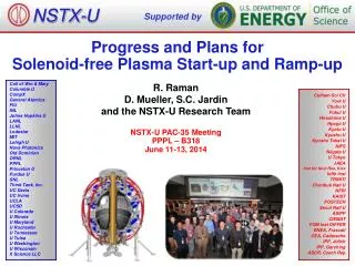
Supported by. A solenoid-free current start-up scenario utilizing outer poloidal field coils and center-post. Columbia U Comp-X General Atomics INEL Johns Hopkins U LANL LLNL Lodestar MIT Nova Photonics NYU ORNL PPPL PSI SNL UC Davis UC Irvine UCLA UCSD U Maryland

E N D
Supported by A solenoid-free current start-up scenario utilizing outer poloidal field coils and center-post Columbia U Comp-X General Atomics INEL Johns Hopkins U LANL LLNL Lodestar MIT Nova Photonics NYU ORNL PPPL PSI SNL UC Davis UC Irvine UCLA UCSD U Maryland U New Mexico U Rochester U Washington U Wisconsin Culham Sci Ctr Hiroshima U HIST Kyushu Tokai U Niigata U Tsukuba U U Tokyo JAERI Ioffe Inst TRINITI KBSI KAIST ENEA, Frascati CEA, Cadarache IPP, Jülich IPP, Garching U Quebec Wonho Choe, Jayhyun Kim Korea Advanced Institute of Science and Technology J. Menard, Masayuki Ono, and the NSTX team Princeton Plasma Physics Laboratory Yuichi Takase Tokyo University 46th Annual Meeting of Division of Plasma Physics American Physical Society November 15 – 19, 2004 Savannah, Georgia
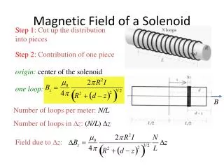
Conventional ohmic solenoid R Plasma a Out-board region In-board region Outer PF coil-only inductive plasma start-up • Ohmic solenoid has been the work horse of fusion research for decades. • Attractive fusion CTF and power plant design requires OH elimination • Compact CTF requires elimination of OH regardless of R/a. • ARIES-AT and ARIES-ST design assumes no OH. • PF coils have been used to start-up the plasma • MAST / START: Merging/compression using in-vessel PF coils • JT-60U / TST-2: ~150 kA / 10 kA obtained using strong (1 MW / 100 kW) ECH pre-ionization with ~0.02 kV/m • Plasma start-up using appropriate combination of out-board and outer PF coils, and/or using a conducting center-post.
#1 Z Plasma Plasma #2 #1 R #3 a a Midplane #2 #3 Plasma R Major axis Null field region Initial plasma matched Field null region Null field generation using out-board induction coils • Small radius PF coil #1 produces a ‘peaked’ BV profile. • Large radius PF coil #2 produces a flat BV profile. • Near-midplane ‘trim’ PF coil #3 produces a follow BV profile.
Coil #1 (+16 MA-t) Coil #2 (-10 MA-t) Coil #3_1 (-3.7 MA-t) Coil #3_2 (+6.7 MA-t) Net vertical field profile Available flux Field null region matched Sufficient mid-plane space for blanket access (NSST) Mid-plane vertical field profiles
Case 5 cont’d Radial profile of flux Mod-B contours (Gauss) Plasma axis Outer PF Start-Up could provide multi-MA ‘seed’ current for future STs NSST Flux contours • Significant amount of volt-sec available for current ramp-up: ~4.5 V-s at R0 = 1.75 m • Generation of good quality multi-pole field null • Excellent out-board access (~1.8 m vertical spacing) • Suitable for the interchangeable blanket modules for CTF.
Breakdown contours (0.1 kV/m and 0.02 kV/m) (NSST) Time-dependent calculation NSST 592 ms 596 ms 600 ms ~1.2 m 604 ms 608 ms 612 ms 0.02 kV/m 0.1 kV/m • Successful start-up with ET·BT/BP ≥ 0.02 kV/m • (Takase et al., EX/P4-34) • Large 0.02 kV/m contour (~1.2 m diameter)
+20 kA/turn - 20 kA/t +2.8 kA/t 0.02 kV/m 0.1 kV/m Simulation for NSTX Breakdown contours Flux contours
Time-dependent calculation with vacuum vessel eddy currents considered* Mod-B contours (Gauss) 24 ms 25 ms 23 ms • Lloyd’s condition, with strong pre-ionization, ET·BT/BP ≥ 0.1 kV/m satisfied in a significant volume. 28 ms 27 ms 26 ms • Successful start-up with • ET·BT/BP ≥ 0.02 kV/m • (Takase et al., IAEA EX/P4-34) • Large 0.02 kV/m contour contours (kV/m) 23 ms 24 ms 25 ms ~ 35 cm 28 ms 26 ms 27 ms *J. Kim, W. Choe, M. Ono, Plasma Phys. Control. Fusion 46 (2004) 1647
Loop voltage and poloidal flux Coil current Loop voltage Flux vs time (at 1.4 m) PF3 PF2 PF5 Null Null Null PF4 • Significant V-s is available for current ramp-up. • Full ramp-up scenario will require bi-polar PF5. But, initial breakdown experiment to ~100 kA should be possible with the existing power supplies.
for stability Force balance and stability issues • Force balance in the initial start-up phase needs to be checked carefully. • Self-consistent code including evolution of plasma current and parameters Stable field structure against axis-symmetric mode Vertical field for force balance
Shot 114405 Preliminary PF-only Start-up Experiments in NSTX Pre-ionize plasma near RF antenna with ECH + 400 kW HHFW, nD2 = (1 - 2)10-5 Torr Create high-quality field-null with (5 - 15) loop-volts at antenna So far, require EfBf /BP > 0.1 kV/mover substantial plasma volume Have created 20 kA plasmas that terminate near center-stack J. Menard
(Null size: ETBT/BP > 0.1kV/m) OH XP433-I XP433-II XP448-I XP448-II XP431 Successful initiation thus far requires a large null region Successful initiation: OH:112152, 4.5 kG XP433-I: 113612, 3.5 kG XP433-II:114405, 3 kG Unsuccessful initiation: XP431: H:11293, 4.5 kG XP448-I: 113609, 3.5 kG XP448-II:114484, 3 kG
Coil current waveforms used in XP-443 Similar to OH startup waveforms PF2 PF4 114405
114405 Field and loop voltage At plasma breakdown Near maximum plasma current
8ms 9ms 10ms Camera images and reconstructions show plasmas are born on LFS and have an inward radial trajectory 114405 • LRDFIT code used for reconstructions • IVessel 10 IP • Careful control of BZ after breakdown helped raise IP from 10kA to 20kA • More BZ evolution optimization possible
114405 t=10ms Thomson measurements consistent with plasma motion and peaked pe profiles Thomson Te < 35eV and camera images consistent with lack of burn-through need more plasma heating power: More HHFW power during breakdown Higher VLOOP – keep plasma outboard EBW power could be very helpful C. Bush, ORNL B. LeBlanc
Solenoid-free current-start-up scenario including PF4 113609 • Try to store more poloidal flux at null regionfor IP ramp • Start PF2 & 3 coils with large positive bias • Balanced by negative PF4 • Store 50-100mWb at null • Null size 1/3 of XP448 • Null formation very sensitive to coil current time-history and vessel current model
Shot 113608 - C. Bush, ORNL Camera Gain = 95 3 ms 4 ms 6 ms 7 ms
s113609 (N. Nishino - Hiroshima fast camera) 3.330 ms 3.552 ms 3.108 ms 2.442 ms 2.664 ms 2.886 ms 4.662 ms 4.884 ms 3.774 ms 3.996 ms 4.218 ms 4.440 ms 5.106 ms 5.328 ms 5.550 ms 5.772 ms 5.994 ms 6.216 ms 6.438 ms 6.660 ms 6.882 ms 7.104 ms 7.548 ms 7.326 ms
Magnetics bound IP to < 15kA (probably only few kA) Bright emission (Hiroshima camera) in 2.5 – 8 ms B-dot loop signal (near PF4) 113611 (vac. shot) Rogowski B_L1DMPPPGL7 • RF noise • IPF4 diff. IPF4 B_L1DMPPPGU8 Ip = ~ 15 kA ~50 G B_L1DMPPPGU7 B_L1DMPPPGL8
Results • HHFW pre-ionization necessary • Need sufficient neutral density, 0-0 phasing • Increase from 0.5 MW to > 1 MW w/ more straps • EBW could be very helpful (was on TST-2) • Large null required for IP initiation thus far • Need more work on finding optimal balance of stored flux vs. null size vs. initial plasma shape • Good plasma position evolution following breakdown crucial to high IP • DINA modeling should be helpful here
Inductive plasma start-up scheme using a conducting center-post Single turn TF leads to an attractive ST CTF R = 1.2 m, a = 0.8 m .
Solid center-post envisioned for ST reactor could provide additional poloidal flux PF Coils Center-post Plasma • • Possible as long as the poloidal flux is available at the time of the plasma start-up. • • Assuming the center-post radius is 50 cm for NSST (or CTF-like device), Bz ~ 0.7 T would mean the center-post may provide ~0.55 Wb. • • However, if we use the same coils energized in the same current direction, Bz ~ 8 T can be obtained in the center-post. • ~ 6 Wb is stored in the center-post. • Then, can one reverse PF #2 and #3_1 before the center-post eddy current decays away?
PF1 current t PF2 and 3_1 current t PF3_2 current t Charging up TF column fully charged Plasma current ramp up TF column charging sequence t=T1 T2 Vacuum vessel resistive skin time Center-post resistive skin time Field null formation and plasma initiation
Copper TF center-post charging sequence Copper TF Center-post At t = T1, All PF currents in the same polarity to maximize the charging At t = T2 , PF2 current reverses to create field null before center-post flux decays Copper TF Center-post
Loop voltage Net Plasma initiation time PF2 Flux from CP PF1 VV Induced current waveforms and poloidal flux At (1.0 m, 0) Mid-plane Outermost shell PF1,2 Center-post At 2 sec
Evolution of Bz profile Driving current waveform Bz by center-post PF1,2 Center-post Total Bz profile Bz profile of a typical solenoid Solenoid Due to vessel
Stray field due to the charged center-post Centerpost Central solenoid Null region • Like OH, the stray field is relatively small and uniform in the breakdown region. • The stray field can be easily nulled out by compensation coils (on-going). • The present method is quite compatible with the PF-only start-up concept utilizing the same hardware.
Some thoughts • The center-post flux storage concept can essentially double the available flux by using the same hardware of the outer-PF-only start-up concept. • ~ 10 Wb could potentially solve the CTF start-up and ramp-up issue. NSTX gets 1 MA with 0.35 Wb. So, it should be possible to reach 15 MA with twice the major radius (R = 1.7 m) with 10 Wb ( R2). • The concept works better with high R/a. If we go with R/a = 2 CTF, then one can envision R = 75 cm core, which can essentially double the flux compared to R = 50 cm core. • The induced loop voltage is determined by the stored flux and the flux decay rate. It can be adjusted by controlling the center-post resistivity (material, temperature) or resistance (thickness). • If the inner torus radius is 4 m for example for R = 6 m advanced tokamak reactor, one can conceive a metal ring structure (a combination of vacuum vessel, shield, and support structure) of mean-radius of 3.5 m. In that case, one can store up to 230 Wb of flux assuming 7 T charging field ( x 3.52 x 7)! Even a fluctuation of that would be sufficient for start-up. • Since pure metal is much more radiation resistance and simple compared to highly stressed OH solenoid, it could also be a more attractive reactor option for tokamak as well.
Summary • Two complementary inductively-based concepts to aid the solenoid-free start-up for future ST and tokamak reactors are presented. • A combination of out-board PF coils placed outside the vacuum vessel is shown to create a good quality field null region while retaining significant volt-second capability for current ramp-up. - For NSST, 4 - 5 Wb possible for ramping the current to a few MAs. - For NSTX, ~0.12 Wb possible for Ip ~ a few hundred kA. • Inboard-side conducting material to store the magnetic flux which is initially charged up by the outboard-side outer PF coils. For ST, it is conceivable to utilize the central TF conducting post as the flux storage. - The NSST (CTF) size device can provide additional 2 - 4 Wb with this method. • Like the OH solenoid, the stray field generated by the center-post flux is relatively small which would make it suitable for the plasma start-up utilization.