Download
1 / 13
130 likes | 261 Views
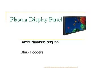
PLASMA DISPLAY MONITOR RASTOR VS RANDOM SCAN INTERLACING AND NON-INTERLACING. PLASMA DISPLAY MONITOR. WHAT IS PLASMA?.

E N D
PLASMA DISPLAY MONITOR RASTOR VS RANDOM SCAN INTERLACING AND NON-INTERLACING
WHAT IS PLASMA? Plasma is often called the "Fourth State of Matter", the other three being solid, liquid and gas. A plasma is a distinct state of matter containing a significant number of electrically charged particles, a number sufficient to affect its electrical properties and behavior. Plasma is a substance similar to gas in which a certain portion of the particles are ionized .
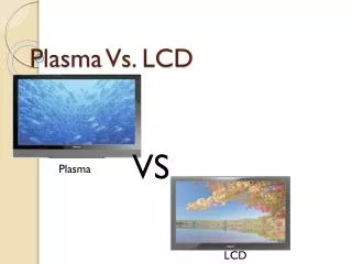
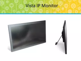
INTRODUCTION • A plasma display is the most advanced technology based display devices (as they are not at all bulky when compared to CRTs). • Provide a very good quality of picture which is sharp from every angle. • They have a slim profile & can be wall mounted. • They have got high refresh rates and a faster response time, contributing to superior performance. • The weight of a plasma display monitor that is, on average about 40% to 50% of the weight of a CRT-based monitor of similar screen size.
INSIDE THE DISPLAY • A plasma display monitor is composed of a front plate with pairs of display electrodes and a rear plate which contains address electrodes. • In the front plate the electrodes are covered with a glass layer called the Dielectric Layer. A magnesium oxide coating, called the Protective Layer, is applied to this glass layer.
IMAGE FORMATION • The display electrodes are arranged in horizontal rows along the screen and the address electrodes are arranged in vertical columns. The vertical and horizontal electrodes form a basic grid. • Within each cell, there are actually three sub cells, one containing a red , another a blue , and a green phosphor. To generate color shades, the perceived intensity of each RGB color must be controlled independently . • To ionize the gas in a particular cell, the plasma display's computer charges the electrodes that intersect at that cell.
When the intersecting electrodes are charged, an electric current flows through the gas in the cell . • The current creates a rapid flow of charged particles, which stimulates the gas atoms to release ultraviolet photons. • The released ultraviolet photons interact with phosphor material coated on the inside wall of the cell.. When an ultraviolet photon hits a phosphor atom in the cell, one of the phosphor's electrons jumps to a higher energy level. When the electron falls back to its normal level, it releases energy in the form of a visible light .
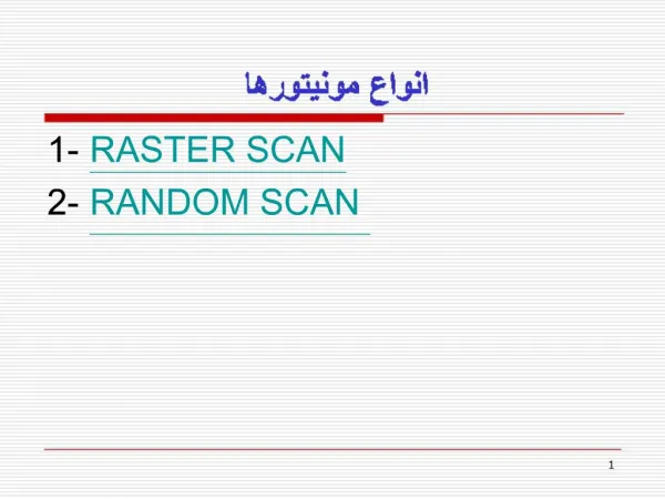
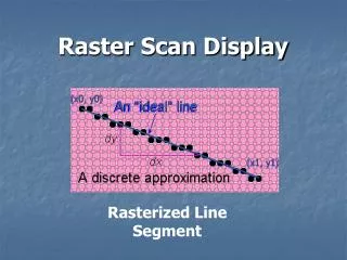
When operated as a random-scan display unit, a CRT directs the electron beam only to the parts of the screen where a picture is to be drawn. In raster scan, the beam sweeps horizontally left-to-right at a steady rate, then blanks and rapidly moves back to the left, where it turns back on and sweeps out the next line (flyback). RANDOM vs RASTER SCAN
Random displays have high resolutions Smooth lines are produced as the electron beam directly follows the line path Random-scan system's are generally costlier Random scan systems are designed to draw all the component lines of a picture 30 to 60 times each second Picture definition is stored as a set of line drawing commands in an area of memory referred to as refresh display file. Raster displays have less resolution Lines produced are ziz-zag as the plotted values are discrete Decreasing memory costs have made raster systems popular. Refreshing on raster scan displays is carried out at the rate of 60 to 80 frames/second Picture definition is stored in a memory area called the refresh buffer/frame buffer.
INTERLACING Interlaced scan refers to one of two common methods for "painting" a video image on an electronic display screen by scanning or displaying each line or row of pixels. This technique uses two fields to create a frame. One field contains all the odd lines in the image, the other contains all the even lines of the image .
NON-INTERLACED DISPLAY It is the opposite phenomenon of Interlacing. In this all the lines of frame are scanned in one pass. For higher resolution the non-interlaced display creates a better image as compared to Interlaced display. The scanning is done line by line in continuous fashion in non-interlaced display.