Download
1 / 46
490 likes | 627 Views
David E. Bauer Troy M. Libby Magnetic Analysis Corporation 535 south 4th AVE Mt Vernon, NY 10550 dbauer@mac-ndt.com tlibby@mac-ndt.com 914-699-9450. Nondestructive testing since 1928. TESTING CRITICAL MEDICAL TUBING USING HIGH FREQUENCY EDDY CURRENT COILS.

E N D
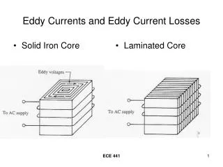
David E. BauerTroy M. LibbyMagnetic Analysis Corporation535 south 4th AVEMt Vernon, NY 10550dbauer@mac-ndt.comtlibby@mac-ndt.com914-699-9450 Nondestructive testing since 1928 TESTING CRITICAL MEDICAL TUBING USING HIGH FREQUENCY EDDY CURRENT COILS
Usually medical materials have very low conductivity and small dimensions that require a high test frequency.
In the past, these materials were tested at a maximum of 1 MHZ due to coil design and limitations to the input stages of electronics.
The composition of the material under test influences the selection • of the test frequency.
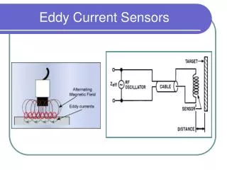
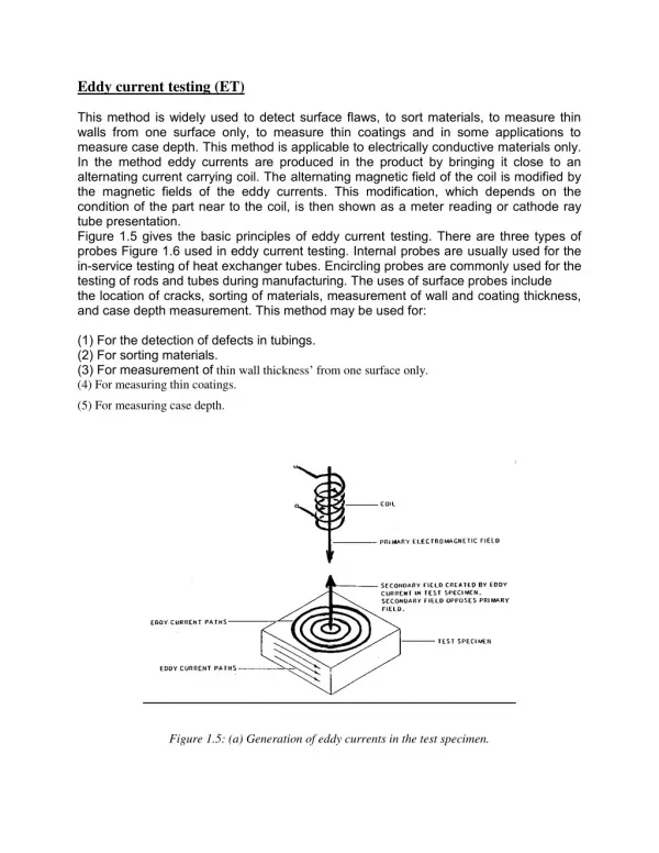
Encircling coil eddy current testing of thin walled small diameter tube is inspected as it travels through a coil excited with one or more high frequency signals
With new electronics which are linear and coil designs which are low impedance, it is possible to test these materials with greater S/N (signal to noise) and use the phase response to reject mechanical, permeability and dielectric noise.
This paper will discuss the advantages obtained by testing these types of materials at higher frequencies using new coils designs.
Absolute or Differential Test Modes • Generally, a differential mode system is more sensitive to intermittent defects because one section of material is being compared to the next
However, with long, uniform discontinuities, a differential mode system may indicate only the beginning and the end, and nothing in between
Conversely, the absolute mode would signal for the complete length of the defect
However, the ability of the differential mode to detect smaller changes and to produce a better flaw signal-to-noise ratio makes it more suitable for general application
HI FREQUENCY MULTIMAC TESTER FOR SMALL DIAMETER MEDICAL WIRE & TUBE • The high performance MultiMac 8 channel eddy current tester successfully inspects small diameter wire .0035" (.089 mm) and tubing with wall thickness of .004" (.10 mm)
Specialized alloys including nickel-titanium, tungsten-rhenium, uranium, trans uranium alloys, Inconels and Hastealloys used in medical applications such as guide wires and stents can be tested.
MultiMac test frequencies ranging up to 5 MHz, high speed circuitry and graphics, allow accurate defect detection at test speeds up to several thousand fpm
Depth of Penetration Discontinuity detection is limited to the penetration depth of eddy currents. Penetration depth is inversely proportional to the square root of conductivity, frequency and permeability
Where: • δ = Standard Depth of Penetration (mm)π = 3.14f = Test Frequency (Hz)µ = Magnetic Permeability (H/mm)σ = Electrical Conductivity (% IACS)
Chart showing depth of penetration for various conductivity metals
Typical coil cable attenuation due to high frequency Much shorter cables are needed at higher testing frequencies
Applications Fig 1- XWNE High Frequency Test Coil with .071” material shown.
Test results at 1MHZ . Notice Material noise is in phase with flaw signal. This is because the electromagnetic skin depth is much greater than the wall thickness of the tube so there is no discrimination between the response of the tubes lateral movement (or diameter change ) of the tube in the coil and the flaw which penetrates the surface.
Test results at 3MHZ . Notice how Material noise is no longer in phase with the flaw signal. The noise here is caused by lateral motion of the tube within the coil, and as the defect has some depth. The tubes motion dependent phase response differs from the phase response of the flaw. This is due to the fact that the electromagnetic skin depth has been reduced at the increased frequency, and this leads to a measurable delay of the signal as it propagates through the wall. This delay is the phase shift of the flaw response.
Other ApplicationsUsing multiple test coils. • FIG 5- Is a Quad coil platform used on a multi line aluminum extruder.
This system uses 4 channel High Frequency unit to simultaneously test for defects on the four lines. The difficult test here is for small defects that lie on the middle of the top or bottom surface, because of the low field density in these region and the presence of the varying Finning that is extruded on the bore of this tube. Flaw down to .010” diameter are easily detected on the middle of the large flat surfaces
FIG 6 • Extruded aluminum tubing with internal fining approximately 1” x .125” in cross section. • FIG 7 • Coils for testing the above aluminum extruded tube
Application using High Frequency Probes on special alloys. Rotary probe testing solid round wire
Conclusion • The principle reason for high frequency testing in small diameter tube and wire is to match the electromagnetic penetration to the dimension of the object under test
The low conductivity of the high alloy wires will also force the frequencies to be higher for these small dimensioned objects
Problems arise from testing at high frequencies because of the very high gains required and cabling systems to the sensor. New noise sources both transient and systemic come into play at high frequencies through the dielectric response sensitivity that becomes an issue above 8 MHz.
Materials produced for the medical industry are usually non-ferrous and have a low permeability that is difficult to test
These tubes or wires are also very small (.071” tube with a.005wall, wire down to.004”).
Testing these new alloys with smaller dimensions the reflection that is returned to the test coil will also be smaller
Therefore it is important to test this type of material at frequencies up 20 MHz
With the advancement of electronics and special coils testing frequencies of up to 200 MHZ will be obtainable
It allows the eddy currents to be densest on the surface of the material, making them closer to the secondary windings of the test coils.
Designing a new coil with a ceramic bobbin or other materials will help to improve the fill factor that is instrumental to this type of testing
Medical alloy is a nonmagnetic, chromium-nickel-tungsten-cobalt alloy possessing good oxidation and corrosion resistance as well as high strength properties at elevated temperatures
Typical Applications for this alloy have included • Gas Turbine Rotors • Nozzle Diaphragm Valves • Springs • Bone Drill Bits • Heart Valves
The high strength properties of this alloy may be obtained through work hardening. It remains nonmagnetic in the work hardened condition
WWW.MAC-NDT.COM CONTACTUS@MAC-NDT.COM