Download
1 / 20
200 likes | 330 Views
59. Measuring IP Network Routing Convergence. A new approach to the problem. A Blind Spot In Network Performance Monitoring. Today’s monitoring technologies tell us how the network performs in steady state It does not tell us how quickly it becomes usable after a failure.

E N D
59 Measuring IP Network Routing Convergence A new approach to the problem
A Blind Spot In Network Performance Monitoring • Today’s monitoring technologies tell us how the network performs in steady state • It does not tell us how quickly it becomes usable after a failure
Network Convergence Is Hard To Measure in Production • Have you measured the convergence speed of your network? How often do you do it? • The obvious way to do this is to measure traffic loss when you induce a network failure • Measuring network convergence is service impacting and a manual process • What if you could measure network convergence without service impact? • What if you could automate it?
An Enabling Technology • Two Way Jitter Measurement Probes • A sending device (sender) transmits a stream of numbered packets with a fixed packet interval to a responding device • The responding device (responder) returns the packets back to the sender • The sender reports on latency, jitter and packet loss • Examples • RFC5357 TWAMP, RFC6812 Cisco’s Service-Level Assurance Protocol
A new approach • Combine jitter probes with routing protocols to measure network convergence (protocol convergence & FIB insertion) across all routers in a network • The technique is not service impacting and can be performed periodically to baseline and track network performance
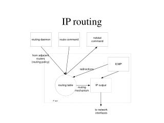
How it works • A probe sender participates in a network routing protocol
The sender initiates a probe to a responder. Probe packets use a source IP address A thatis not routed on the network • Probe return traffic is discarded by a diverting router which originates a default route or some aggregate route which includes A
While the probe is running, at some time t0 the sender announces a route for A into the network
After some time passes at time tc the network converges • At some later time tan the nth packet in the probe is returned to the sender • The convergence time Tc = tc – t0 < tan – t0
At the time the packet n-1 was sent by the sender (tsn-1 ) the network had not converged – otherwise packet n-1 would have returned to the sender. Therefore: tsn-1 – t0 < Tc < tan – t0 • An upper and lower bound on the convergence time for the network between the sender and responder can be measured • Convergence interval is: tan – tsn-1 = probe packet interval + rtt + responder dwell time
The technique can be applied to any routing protocol or combinations of protocols and is equally applicable to IPv4 and IPv6 • Sender clock does not have to be synchronized with any other device • Convergence of multiple paths across the network can be measured by launching simultaneous probes to different responders
MPLS Networks • Convergence time of protocols running in VRFs connected to an MPLS VPN can be measured • By measuring the IGP convergence time of BGP nexthops in an MPLS network IGP+LDP convergence can be measured
Theoretical Model for SPF Convergence • D – Failure Detection • O – LSA Origination • F – Flooding time • SPT – Shortest-path tree computation time • RIB – RIB/FIB update • DD– linecard FIB update distribution Tc = D + O + F + SPT + RIB + DD * • Underlined terms are measured by this technique * Francois P, Filsfils C, Evans J, Bonaventure O. Achieving sub-second IGP convergence in large IP networks, 2009
Why this is useful • Network qualification • Confirm SLA compliance • Baselining and tracking convergence allows changes in network performance to be detected • Network architecture validation (before and after testing) • Troubleshooting network & routing performance
Sample Network • Lab network with few routes and little traffic – results shown will not be representative of a production network
OSPF SPF Convergence • Actually the network was initially configured for fast convergence – except for r1 • One poorly configured router can spoil the party for everyone.
OSPF SPF Fast Convergence • Convergence is topology dependant. r1 converges first, the others follow • Strange jump in convergence after r2. Why? Studying these graphs quickly leads to questions about implementation in specific routers.
OSPF External LSA Convergence • Same pattern as with SPF convergence
BGP Convergence • BGP is very fast on this small network • r2 seems to converge more slowly than r4 and r6. This is actually an indicator that it is slow in processing IP SLA packets. Cisco recommends the use of shadow routers as IP SLA responders
Thank You For further information please contact Laris Benkis (613) 261 8052 laris@tpn.cc