Download
1 / 34
340 likes | 474 Views
US LHC Accelerator Research Program. BNL - FNAL- LBNL - SLAC. Summary of Accelerator Systems Collimation Parallel Session. 19 October 2007 LARP CM#9 - SLAC Tom Markiewicz/SLAC. CRYSTAL COLLIMATION EXPERIMENT AT THE TEVATRON Nikolai Mokhov Fermilab. Mission Statement

E N D
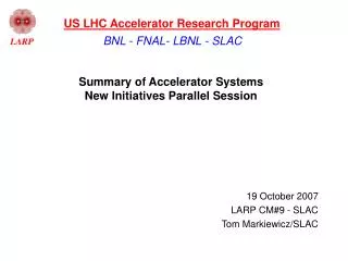
US LHC Accelerator Research Program BNL - FNAL- LBNL - SLAC Summary of Accelerator Systems Collimation Parallel Session 19 October 2007 LARP CM#9 - SLAC Tom Markiewicz/SLAC
CRYSTAL COLLIMATION EXPERIMENTAT THE TEVATRONNikolai MokhovFermilab • Mission Statement • We propose an experiment at Fermilab’s Tevatron to measure the predicted improvement in collimation efficiency that could be obtained by replacing amorphous primary collimators with bent crystals. • Considering the unique possibility provided by the Tevatron Collider, and having already established fruitful collaborative efforts on crystal characterization, tests and use for collimation, we propose to test and confirm models of multi-turn dynamics with crystals by exploiting channeling and newly understood phenomena such as volume reflection as well as to further study collimation. Collimation Summary - T. Markiewicz
(Analysis by V. Shiltsev) 2005 Tevatron Experiment With E03H out, LE033C BLM is proportional to nuclear interact. rate in crystal Channeled beam “peak” width is 22±4 mrad (rms) Collimation Summary - T. Markiewicz
320 urad 150urad channel 2006 Installation of Shorter Crystal with Smaller Bend and 2007 Run/Analysis • Original installation had misaligned crystal • Angular reproducibility for a horizontal translation of the table terrible • 1 mil horizontal translation can produce an angle error of 100urad • Building a new goniometer with new specifications for motion tolerance and vacuum is needed Angular motion Into the beam Collimation Summary - T. Markiewicz
Noise on BLM signals Other Issues with 2007 Run • Noisy Losses on Detectors: • Noisy losses produced on the PIN and BLM monitors look like channeling signatures. • These are real effects caused by motion of the beam, effects of abort gap cleaning, etc. • Solutions to these are refining operational procedures and attempting to build better orbit stabilization software around the area of the bent crystal. • Improving Beam Diagnostic Capabilities • Current beam diagnostics used to detect channeled and VR beam is a PIN diode system and a Tevatron ionization style BLM. (picture in next slide) • The PIN diode is reasonable for detecting the rate of nuclear interactions at the crystal. • In order to view the channeled and VR beam downstream of the crystal better diagnostics are needed. Roman Pot style detectors have been considered and offered. Collimation Summary - T. Markiewicz
How to Meet Mission Goals? Demonstrate high efficiency volume reflection seen in RD22 extraction line experiment in collider environment using EDGE of crystal Collimation Summary - T. Markiewicz
Plans for FY 2008: 3 Choices • Beam Studies: Nothing new, keep playing around • Continue to use the installed crystal assembly and strip crystal to demonstrate main goals. • This may require more study time due to increased setup now that problems with goniometer have been characterized. • Would like to have 2 to 3 of End of Store study periods as early as Dec. 2007 to demonstrate well characterized channeling from the strip crystal now that more is understood about the goniometer motion. • New Goniometer(s): No new diagnostics, but replace goniometer • Start specifications and engineering for new horizontal goniometer that would replace current assembly. • Currently have identified a FNAL engineer to work on this. • If full 2 plane crystal collimation is going to be demonstrated that would require an additional vertical goniometer to be built. • A full simulation would be required for best placement of the vertical goniometer as well locations of channeled and volume reflected beams. • Beam Diagnostics: The whole enchilada: Raison d’etre for collaboration • Start specifications and assessing new or additional beam diagnostics that will be needed. Collimation Summary - T. Markiewicz
E01 collimator E02 collimator F171 collimator Tevatron Warm Space for New Hardware Proton Set 1 D49 Tar, E03 & F172 2nd Proton Set 2 D171Tar, D173 & A0 Pbar Set 1 F49 Tar, F48 & D172 Pbar Set 2 F173 Tar, F171 & E02 All these devices will have to be removed to accommodate space for new hardware These locations have additional warm space but may not be optimal. Collimation Summary - T. Markiewicz
Time • Timing for Installing New Hardware: • Should be stressed that any new hardware installed into the Tevatron for use in 2009 will have to be ready for the Summer 2008 shutdown. • Ferrara needs 6 months minimum to fabricate goniometers and will not spend $/effort without FIRM COMMITMENT to run the experiment Collimation Summary - T. Markiewicz
COLLABORATION, LOI AND MEETING ON DEC. 6-7 • Very encouraging support from • LARP management • Fermilab management • CERN management • INFN management • August Accelerator Advisory Committee at Fermilab • It was proposed that we prepare a Letter-of-Intent (LOI), “Crystal Collimation Experiment at the Tevatron” and form an official collaboration. Collimation Summary - T. Markiewicz
Immediate Requirement • Need full realistic multi-turn simulations – for the current lattice and crystal/collimator configuration to confirm 1999-2003 results, justify a choice of a short crystal and identify locations for comprehensive beam diagnostics (single particle tracking capability?) and second (vertical) crystal/goniometer • Can this happen in time for Dec 6-7 Collaboration Meeting in sufficient detail to motivate invasive hardware installation, diagnostic construction and formation of a 50-100 member international collaboration? • Nikolai & Sasha Drozhdin committed • Known to be needed in April 2007, but zero produced Collimation Summary - T. Markiewicz
beam beam Rotatable CollimatorsJeff Smith Collimation Summary - T. Markiewicz
Design of Jaw-Shaft-Mandrel 20 facets Glidcop Cu Mo Cu coolant supply tubes twist to allow jaw rotation Helical cooling channels 25mm below surface Hub area Cantilever Mo shaft @ both ends Collimation Summary - T. Markiewicz
Design of Jaw Support and Rotation Mechanism U-Joint Flexes for Shaft “sag” and “Slewing” Triple Cog Geneva Drive Wheel required for 512 clicks per facet Water Cooling Inlet and outlet Collimation Summary - T. Markiewicz
Design Complete Except for RF Features Jaw Geneva Mechanism Worm Gear Shaft 1-2mm Gap Water Cooling Channel U-Joint Axle Support Bearings Diaphragm Collimation Summary - T. Markiewicz
Current Vision of RF Transitions Spiral style backing springs reside inside “Sheath” (sheath not shown) Thin sheet metal RF “Curtain” Round to Square Transition Transition “Socket” Spherical profile “Fingers” Collimation Summary - T. Markiewicz
Up Beam end detail view away from beam side 2 cam buttons (not shown) lift “Socket” off “Fingers” during Jaw rotation and rest in detents during collimation Jaw cooling return line Spring flexes to maintain contact force on “Fingers” for longitudinal and lateral displacements of the Jaw ends Collimation Summary - T. Markiewicz
Braze Test#2 Delivered 19 Dec 2006 Collimation Summary - T. Markiewicz
Vacuum Bake of Braze Test#2 Results: 4/1/07~3x over LHC Spec • 1st Jaw Braze Test Assembly has been vacuum baked at 300 degrees C for 32 hours. • LHC Requirement = 1E-7 Pa = 7.5E-10 Torr • Baseline pressure of Vacuum Test Chamber: • 4.3E-7 Pa (3.2E-9 Torr) • Pressure w/ 200mm Jaw Assy. in Test Chamber: 4.9E-7 Pa (3.7E-9 Torr) • Presumed pressure of 200mm lg. Jaw Assy.: 6.0E-8 Pa (4.5E-10 Torr) • Note: above readings were from gauges in the foreline, closer to the pump than to the Test Chamber. Pressures at the part could be higher. • Outcome: • SLAC vacuum group has suggested longitudinal grooves be incorporated into the inner length of jaws; incorporated into next prototype Collimation Summary - T. Markiewicz
6/25/07-7/2/07 Slice & Dice Braze Test#2 Interior slice: polished & etched Longitudinal slice ∙ Evidence of fracturing along grain boundaries presumed due to too-rapid cooldown after braze - areas near ends and OD look better∙ Braze of jaws to hub GOOD∙ 3 of 4 jaw-jaw brazes GOOD ∙ Same fracturing patterns as in other slice∙ Braze of cooling coils to jaw ID good∙ Braze of cooling coil bottom to mandrel so-so Collimation Summary - T. Markiewicz
Braze Test #3: Vacuum tests • 3rd Jaw Braze Test Assembly has been vacuum baked at 300 degrees C for 32 hours. Results in slightly lower pressure. • Inclusion of longitudinal groovesin the inner length of jaws for better outgasing • Test Chamber setup similar to previous test. Under Investigation... Collimation Summary - T. Markiewicz
Braze Test #3: Sectioning & ExaminationCu grain boundary cracking during brazing • Specimen 140mm OD x 60mm ID x 200mm L (¼ section shown) • one braze cycle in the 900 C range • grain boundary cracks located in interior regions • believed due to excessive heating rate • Glidcop to be tested • Concerns • Effect on performance • What happens in accident case? Collimation Summary - T. Markiewicz
Glidcop Al-15 Heat sampleWhile 1st jaw used to test thermal mechanical issues is Copper, first full 2 jaw prototype will use Glidcop 2 Heats (at Jaw brazing temperature) No grain boundary cracking is apparent Metallographic samples are being prepared for microscopic inspection Collimation Summary - T. Markiewicz
Apr 6: Cu-Mo Hub Braze Test Assembly after 3 additional heat cycles (to mimic full assembly procedure) then sectioned. Cu “finger” fractured • Grain boundary issues? • Possible fracturing? Cu-Mo joints we care about 1mm expansion gap Samples sliced & polished and sent to Physical Electronics lab for analysis 4/23: Fractures evident Small holes held braze wire Collimation Summary - T. Markiewicz
Compression fit for Cu-Mo joint • Another option is to use a compression fit and diffusion bonding. Test hub fell apart once we made a slice! Copper Jaw is constrained on the outside diameter with Carbon and when heated to ~ 900 degrees C is forced to yield so that upon cooling to ~ 500 degrees C the inner diameter begins to shrink onto the Mo Shaft resulting a substantial interference fit. Collimation Summary - T. Markiewicz
Cu-Mo joint: Segmented Moly for expansion • Another option is to use a segmented flexible molybdenum end to prevent fractures and prevent Co from pulling away from Moly. Will be cutting small samples for metallurgy tests. May make slight modifications for better braze joint Collimation Summary - T. Markiewicz
Molybdenum Half Shafts & Copper Hub Halves braze preparations Retainer Ring Expander Plug Collimation Summary - T. Markiewicz
21 Mar 2007: Full length Mandrel: In-House & Inspected • Now that shaft design complete, order to bore central hole made • Will wind with in-house copper tubing Collimation Summary - T. Markiewicz
Fixture for stacking 16 24cm-long quarter round jaws on full 960mm cooling coil wrapped mandrel(mostly catalog parts: ordered) Collimation Summary - T. Markiewicz
Up Beam Flex Mount Assembly showing Ratchet and Actuator Collimation Summary - T. Markiewicz
Up Beam Flex Mount Assembly showing Ratchet and Actuator Collimation Summary - T. Markiewicz
Agreement in Progress to Buy a damaged “TCS1” collimator and stand from CERN Collimation Summary - T. Markiewicz
LARP Collimator Delivery Schedule Collimation Summary - T. Markiewicz