Download
1 / 42
420 likes | 593 Views
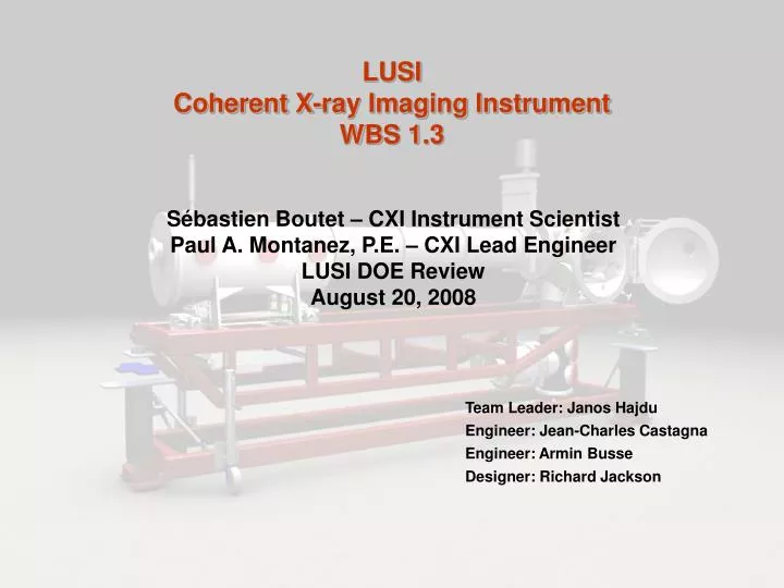
LUSI Coherent X-ray Imaging Instrument WBS 1.3. Sébastien Boutet – CXI Instrument Scientist Paul A. Montanez, P.E. – CXI Lead Engineer LUSI DOE Review August 20, 2008. Team Leader: Janos Hajdu Engineer: Jean-Charles Castagna Engineer: Armin Busse Designer: Richard Jackson. Outline.

E N D
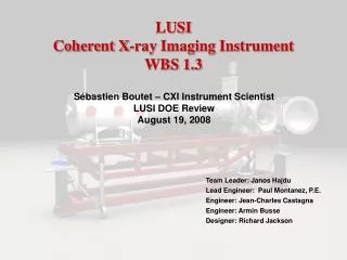
LUSICoherent X-ray Imaging InstrumentWBS 1.3 Sébastien Boutet – CXI Instrument Scientist Paul A. Montanez, P.E. – CXI Lead Engineer LUSI DOE Review August 20, 2008 Team Leader: Janos Hajdu Engineer: Jean-Charles Castagna Engineer: Armin Busse Designer: Richard Jackson
Outline • Physics Requirements • Safety • Instrument Configuration • Engineering/Design Status • Value Engineering • Basis Of Estimate • Procurement Strategy • Cost & Schedule • Critical Path • Risk Analysis • Summary
Science Team • Specifications and instrument concept developed with the science team. The CXI team leaders • Janos Hajdu, Photon Science-SLAC, Uppsala University (leader) • Henry Chapman, DESY, University of Hamburg • John Miao, UCLA
Component Physics Requirements • 1.3.2.1 CXI 0.1 micron KB System • Purpose • Produce a 100 nm focal spot at sample • Located 0.8 meters upstream of sample • For samples smaller than 50 nm • 1.3.2.2 CXI 1 micron KB System • Purpose • Produce a 1 micron focal spot at sample • Located 8 meters upstream of sample • For samples smaller than 0.5 micron ESRF KB Design
Component Physics Requirements • 1.3.2 CXI KB Systems Requirements • >75% reflectivity over the widest energy range possible • Energy Range • At least up to 4-8.5keV • Goal: 2-15 keV • Accept 5 sigmas or more over the widest energy range possible • Withstand full power of the LCLS beam without damage • Preserve coherence • Meet at least the Maréchal criterion at 8.3 keV, the highest fundamental energy • >80% of incident intensity in the central peak at the focal plane • hrms= rms height error over entire length of the mirror • l=wavelength • N=number of reflective optics (2 in this case) • a=incidence angle • Ultra-High vacuum • < 10-9 Torr • Interface with Sample Chamber • Solution • 350 mm mirrors • 3.6 mrad incidence angle • Rh/B4C bilayer • 0.75 nm rms height error over entire mirror
Component Physics Requirements • 100 nm focus is required for imaging small particles • Focal length • First mirror • 900 mm • Second mirror • 500 mm • Focus • 68 x 120 nm spot • Requires reentrant KB design • Closest point of approach to interaction region • 300 mm • Final sample chamber design cannot occur until we have a final KB design
Component Physics Requirements • 1.3.3.1 CXI Reference Laser • Purpose • Rough alignment of the experiment without the X-ray beam • Requirements • On/Off states • Beam size • Smallest possible at the end of the hutch • Stability • 5% of FWHM (short term) • 15% of FWHM (long term) • Useable with any part of the instrument vented to air • Window valves • Aligned to the unfocused FEL beam to within 100 microns
Component Physics Requirements • 1.3.4.1 CXI Coherent Imaging Injector • Purpose • Deliver support-free single particles to the LCLS beam • Requirements • Particle beam focus • < 250 microns • Transmission • > 50 % • Translation (XZ) • 10 mm • Particle size range • 10 – 1500 nm • Aerodynamic lens • Stack of concentric orifices with decreasing openings. • Particle beam diagnostics • Charge detectors • Design builds on recent work at LLNL Bogan et al, Nanoletters 8, 310-316 (2008)
Component Physics Requirements • 1.3.5.1.1 CXI Sample Chambers • Purpose • Position samples on grids and apertures • Maintain high vacuum • Requirements • Accommodate multiple experiments configurations • Fixed targets • Injected particles • Interface with • KB mirrors upstream • Detector Stage downstream • Ports for • Injector • Ion TOF • Lasers • Vacuum better than 10-7 torr • Rapid access • Large volume for flexibility • 1 micron Sample Chamber • Compatible only with 1 micron KB System • Delivered at CD-4B • 0.1 micron Sample Chamber • Similar to 1 micron Sample Chamber • Plus • Compatible both KB Systems • Delivered at CD-4C
Component Physics Requirements • 1.3.5.1.1 CXI Sample Chamber (Fixed targets) • Multiple apertures • Aperture Purpose • Remove beam halo • Remove slit scatter from upstream slits • Aperture Requirements • Apodized edges • Positional resolution and repeatability : <1 µm • Easily replaced if destroyed by the beam • Multiple samples held on multiple grids • Sample pitch and yaw • High resolution telescope for sample viewing • 1.3.5.1.1 CXI Sample Chamber (Injected Particles) • Sample stage can be translated and used as an aperture • Utilize the same setup for fixed samples and particle injection • Particle beam comes in from the top • Particle beam aperture Particle Beam Aperture Apertures Sample
Component Physics Requirements • 1.3.5.1.1 CXI Ion Time-of-Flight • Purpose • Detect ions produced by exploding sample • Provide a veto trigger signal when a particle was hit by the beam • Identify unwanted particles • Requirements • 1 Atomic Mass Unit resolution • Up to 100 AMU detection • 1 GHz digitization • Does not interfere with imaging detector Design will be a scaled down version of the AMO Ion TOF
Component Physics Requirements • 1.3.5.1.2 CXI Precision Instrument Stands • Purpose • Position the chamber at the interaction region • Requirements • Positioning accuracy • 100 microns • Short term stability • 0.1 microns • 5 µrad • 1 micron Precision Instrument Stand • Support the 1 micron Sample Chamber and Detector Stage • 0.1 micron Precision Instrument Stand • Support the 0.1 micron KB System, 0.1 micron Sample Chamber and Detector Stage
Component Physics Requirements • 1.3.5.1.3 CXI Detector Stage • Purpose • Center the detector hole on the direct beam • Position the detector at the appropriate distance from the interaction region • Requirements • Range along the beam : 50-2400 mm • Non-continuous • Vacuum better than 10-7 torr • Diagnostics behind the detector for alignment • Valve to isolate the detector vacuum • Short term stability • 1 micron • 10 µrad
Component Physics Requirements • 1.3.5.1.3 CXI Detector Stage • Purpose • Center the detector hole on the direct beam • Position the detector at the appropriate distance from the interaction region • Requirements • Range along the beam : 50-2400 mm • Non-continuous • Vacuum better than 10-7 torr • Diagnostics behind the detector for alignment • Valve to isolate the detector vacuum • Short term stability • 1 micron • 10 µrad
Component Physics Requirements • 1.3.6 CXI Hutch facilities • Raised flooring • Storage cabinets, work benches and tool chests • Utilities distribution • 1.3.7 CXI Vacuum system • Requirements • Vacuum better than 10-7 Torr • Better than 10-9 Torr for KB Systems • 10 year lifetime for ion pumps • Support stands • 1.3.8 CXI Installation
Safety • LUSI Hazard Analysis Report (PM-391-001-34) complete • Safety issues are considered at every stage of the design, fabrication and installation process • Safety considerations (some examples) • Ionizing Radiation • Hutch walls will comply with SLAC Radiation Safety memo RP-RPG-080606-MEM-01 • Hutch PPS • Pressure/Vacuum Vessel Safety • Compliant with 10CFR851 • Seismic Safety • Designs compliant with: Seismic Design Specification for Buildings, Structures, Equipment, and Systems, SLAC-I-720-0A24E-002-R002 • Mechanical • Engineered solutions that prevent potential “pinch-points” with moving machinery • Hoisting and Rigging • Positioning of devices that require the use of the FEH H5 overhead crane shall be performed by qualified personnel only with an approved lift plan.
Instrument Configuration • CXI is comprised of five major subsystems • Focusing Optics (WBS 1.3.02) • Provide focal spot sizes on the order of 100 nm x 100 nm and 1 µm x 1 µm for the CXI instrument • Reference Laser (WBS 1.3.03) • Provides a visible, low power laser beam collinear with the LCLS X-ray beam to align the components of the CXI instrument without use of the X-ray beam • Sample Environment (WBS 1.3.04 & 1.3.05) • To measure the coherent diffraction pattern of any submicron sample of interest • (1) sample chamber, (2) ion time-of-flight mass spectrometer, (3) particle injector, (4) detector stage and (5) precision instrument stand • Vacuum System (WBS 1.3.07) • Create and support a vacuum environment with pressure better than 10-9 Torr for each KB system and better than 10-7 Torr along the CXI beamline • Diagnostics/Common Optics (WBS 1.5) • Analyze and optimize the X-ray beam properties • Located in both the XRT and FEH H5 and consist of a suite of X-ray optic and diagnostic components that are common with the other LUSI instruments as well as CXI specific hardware, i.e. Wavefront Monitor
CXI Components in the X-ray Transport Tunnel (XRT) Reference Laser (WBS 1.3.03) Beam Direction Diagnostics (WBS 1.5) CXI Components in Far Experimental Hall Hutch 5 (FEH H5) FEH Common Room 2X Double Racks CXI Control Room Gas Cabinet FEH H5 Beam Direction Laser Table Sample Environment (WBS 1.3.04 & 1.3.05) Focusing Optics (WBS 1.3.02) 5X Single Racks Note: Overhead crane inH5 not shown for clarity Instrument Configuration (2)
Engineering/Design Status • CD-2 Documentation Activities • Overall CXI Instrument Physics Requirements Document (PRD) reviewed and approved by team leaders in Dec 07 • CAD system model documentation hierarchy (CAD Drawing Tree/File Structure) in review • Initial XRT/FEH H5 beamline layout complete • 13 PRDs/ESDs released, 9 ESDs in-work/draft-review/released status • 1µm KB system ESD/Technical Specification in review • Hutch Design (FEH H5) • ESDs/Room Data sheets released • Hutch Layout Drawings • Stay Clears • Utilities • Hutch Layout • APP and Risk Identification/Registry complete and up to date • All Basis of Estimates complete and up to date
Instrument Equipment List/Review Checklist Engineering/Design Status (2) • PDR: Preliminary Design Review • CXI Reference Laser & Detector Stage nearing PDR • FDR: Final Design Review • Seismic: Seismic Review • Components > 400lbs • Additional Reviews that may be applicable: • Electrical Safety • Fire Safety • Hazardous Experimental Equipment • Hoisting and Rigging Safety • Laser Safety • Radiation Safety • Preliminary and Final Instrument Design Reviews (PIDR & FIDR)
ESRF KB Design Engineering/Design Status (3) • CXI 0.1µm KB system (WBS 1.3.02.01) • 0.1µm spot size for samples less than 50nm in size • State of the art focusing optic • One potential vendor identified • Osaka U/JTEC – actively pursuing and pushing the technology • Pre-figured/mechanically bent/bimorph solutions acceptable • PRD released June 2008 • Vendor PDR scheduled for November 2009 • Overall system PDR scheduled for February 2010 • ~$1,400K • CXI 1µm KB system (WBS 1.3.02.02) • 1µm spot size for samples between 50nm and 1µm • Technology is proven • Pre-figured/mechanically bent/bimorph solutions acceptable • PRD released June 2008 • ESD/ Technical Specification draft completed (in work-finalize) • Draft of ESD sent to multiple vendors for Request for Information (RFI): • Engineering feasibility study • Budgetary Inquiries • Vendor PDR scheduled for August 2009 • Overall system PDR scheduled for October 2009 • ~$1,390K ($970,000 in long lead procurement – July 2009)
Engineering/Design Status (4) • CXI Reference Laser (WBS 1.3.03.1) • Installed in the X-ray Transport tunnel • Used to align components without requiring FEL beam • Pointing stability critical • Preliminary design nearly complete • Detailed engineering analysis required to ensure pointing stability • PRD released June 2008 • ESD draft completed (in review) • PDR scheduled for October 2008 • ~$115K
Engineering/Design Status (5) • Particle Injector (WBS 1.3.04.01) • Injector design exists from LLNL • LUSI project will advance the design • Recently hired LLNL physicist who was primarily responsible for the design, fabrication and testing of the injector • Work on the injector scheduled to begin July 2008 • PDR scheduled for August 2009 • ~$1,005K
Engineering/Design Status (6) • CXI Sample Chambers (WBS 1.3.05.01.01) • 1µm Sample Chamber • Significant design work completed on the sample chamber for all of its required configurations • Fixed target, particle injection set-ups and options for detector position – complex design • Design should be sufficiently flexible to allow for potential use of Particle Injector/IToF before CD-4C if available • Allow for interface with Detector Stage • PRD released July 2008 • ESD draft completed (in review) • PDR scheduled for December 2008 • ~$750K • 0.1µm Sample Chamber • Design should accommodate all of required experimental configurations • Fixed target, particle injection set-ups and options for detector position • Allow for interface with 0.1µm KB System, Detector Stage, Particle Injector and IToF • PRD released July 2008 • ESD draft completed (in review) • PDR scheduled for March 2010 • ~$500K
Engineering/Design Status (7) • CXI Precision Instrument Stands (WBS 1.3.05.01.02) • 1µm Precision Instrument Stand • Conceptual design based on LCLS AMO Instrument Stand (similar stability/ precision motion requirements) • Support /Interface with 1µm Sample Chamber and Detector Stage • Motorized motions for KB offsets • PRD released July 2008 • ESD draft completed (in review) • PDR scheduled for December 2009 • ~$240K • 0.1µm Precision Instrument Stand • Design similar to 1µm Precision Instrument Stand • Support 0.1µm Sample Chamber, Detector Stage and 0.1µm KB System • Motorized motions for KB offsets • PRD released July 2008 • ESD draft completed (in review) • PDR scheduled for May 2010 • ~$240K
Engineering/Design Status (8) • Detector Stage (WBS 1.3.05.01.03) • Centers the detector on the beam and positions it in “Z” relative to the interaction point • Concept completed • Analysis required to ensure detector stability • Design waiting detector packaging details • PRD released • ESD draft completed (in review) • PDR scheduled for September 2008 • ~$325K
Engineering/Design Status (9) • CXI Hutch Facilities (WBS 1.3.06.0.1 & 1.3.06.02) • Hutch layout design • Raised flooring • Storage cabinets, work benches and tool chests • Utilities distribution • ~$380K • CXI Vacuum System (WBS 1.3.07.01 & 1.3.07.02) • Requirements • Beamline vacuum better than 10-7 Torr • Better than 10-9 Torr for KB Systems • 10 year lifetime for ion pumps • Vacuum equipment: pumps, valves, gauges, etc. • Bellows and Spools • Support stands • PDRs • Vacuum Equipment – scheduled for November 2008 • Vacuum Supports – scheduled for May 2009 • ~$700K
Engineering/Design Status (10) • Installation (WBS 1.3.08.01) • CXI has a “phased installation” • CD-4B • Diagnostics/Common Optics • Reference Laser • 1µm Sample Chamber & Precision Instrument Stand • 1µm KB System • Detector Stage • Vacuum • Equipment/Hardware/Supports • Early Finish – March 2011 • CD-4C • Diagnostics/Common Optics • 0.1µm Sample Chamber & Precision Instrument Stand • 0.1µm KB System • Particle Injector/IToF • Vacuum • Equipment/Hardware/Supports • Early Finish – November 2011
Engineering/Design Status (11) • Preliminary component designs • Reference Laser • Preliminary design ~90% complete • Engineering analysis required to evaluate stability criteria • CXI 1µm Sample Chamber • Preliminary design ~75% complete • CXI 1µm Precision Instrument Stand • Conceptual design based on AMO instrument • Detector Stage • Preliminary design ~75% complete • Awaiting more information on detector packaging and stability analysis • Engineering Specification Document for the 1µm KB system • Currently in “draft-review” status • Multiple vendors evaluating draft specifications
Engineering/Design Status (12) • 6 month “look-ahead” at Level 4/5 Milestones • ESDs released • CXI Detector Stage – Sept 08 • CXI Reference Laser – Sept 08 • CXI 1.0µm KB System – Sept 08 • CXI 1.0µm Precision Instrument Stand – Sept 08 • CXI 1.0µm Sample Chamber – Oct 08 • CXI 0.1µm KB System – Oct 08 • PRDs released • CXI Injector – Jan 09 • Preliminary Design Reviews • CXI Detector Stage – Sept 08 • CXI Reference Laser – Oct 08 • CXI Vacuum Equipment – Nov 08 • CXI 1.0µm Sample Chamber – Dec 08 • Final Design Reviews • CXI Reference Laser – Dec 08 • Vacuum System Equipment – Jan 09 • Cornell Detector Packaging (Participate in) – Feb 09 • Vendor Related • Release CXI KB Systems RFP – Jan 09 • Receive CXI KB Systems Vendor Proposals – Feb 09 • Far Experimental Hall Hutches • FEH H5 Preliminary Layout – Sept 08 • LCLS 30%, 60%, 90% hutch drawing review – Sept 08, Oct 08 and Jan 09 • LCLS FEH FDR – Jan 09
Value Engineering Many trade-offs have been considered in the CXI Preliminary Design The CXI team will continue to purse cost effective approaches for all aspects of the instrument design/fabrication/installation
Procurement Strategy • A variety of sources are used to design/build/install CXI components • SLAC effort where skill set exists. • Vendor design/build used where required. • Previous designs and off-the-shelf components are used whenever available
Cost & Schedule • Resource loaded schedule completed and has been fully implemented into Primavera P3 • CXI (WBS 1.3) • 231 milestones specific to CXI • 197 L4/L5 milestones • L4: Systems (COMP/RCV) • L5: Interface/Handoff (AVAIL/REQD)) • 34 L6 milestones • L6: Commitments/Awards (AWARD) • Duration to “Project Ready for CD-X Approval” • 3B – 14m (Oct 09) • 4B – 31m (April 11) • 4C – 42m (March 12)
Cost & Schedule (2) • BoE & Manpower Loaded Schedule developed in a manner similar to the other LUSI instruments • CXI L3 Planned Budget by Control Acct & FY • Labor – ~ 58% • “Labor” means ALL labor including LOE • Non-Labor – ~ 42% • Peak expenditure in FY10
Cost & Schedule (3) • Durations • Person quarter = 444h • Person year = 1776h • Person month = 148h
Driving Milestones: LL Approval, CD-3 & CD-4 KB Mirrors Design Effort KB Mirrors AWARD & Vendor Design Post Vendor Effort and Installation CXI Critical Path
Installation Effort CXI Critical Path (2) • KB systems are “long duration procurement” items – requesting DOE long lead approval for 1µm KB system prior to CD-3B • Critical path (through 1µm KB System) has 117d of schedule contingency
Risk Identification & Mitigation • Risk Identification/Registry complete and up to date as per “LCLS Risk Management Plan” PMD 1.1-002-r4 • KB Mirror Systems • No vendor willing to bid on systems – Technical & Schedule • Mitigation • Start discussions with vendors early to guarantee their capabilities are consistent with our needs • Iterate specs with vendors early to find a workable solution before bid process • Vendor doesn’t meet specifications – Technical • Mitigation • Travel to vendor sites during fabrication • Have a quality control person supervise their final fabrication process and final surface characterization • Identify vendors with proven capabilities • Delays impact other systems – Schedule • Mitigation • Break the link between the KB0.1 KB mirror and the chamber by building a second chamber to be used early with the KB1 system only. Risk has been alleviated with BCR-2008-06-004: Addition of Second Chamber and Precision Instrument Stand for the CXI Instrument • Sample Chamber • Lack of information regarding 0.1µm KB delays engineering effort – Schedule • Mitigation • Same as “Delays impact other systems” above. Risk retired withBCR-2008-06-004: Addition of Second Chamber and Precision Instrument Stand for the CXI Instrument • Particle Injector • Remote operation – Technical & Schedule • Mitigation • Leverage institutional efforts to solve this problem • Move injector to a CD-4C deliverable
CXI CD-2 Project Readiness CXI designs are mature and technically meet the requirements for CD-2 All CD-2 criteria met
Summary • CXI designs are mature and concepts are based on proven developments made at FLASH and SR sources • CXI has an established design with a consistent cost estimate. Approximately 90% of the materials costs based on vendor quotations, catalogs, or previous orders (Total procurements:3,467K$, Total based on quotes:3,164K$) • Critical Design Thrust • Kirkpatrick-Baez Mirror Systems • Required Long Lead Procurement • 1µm Kirkpatrick-Baez Mirror System • Critical Path “float” reasonable for total schedule duration • Major Risks are mitigated with an implemented BCR to the “preliminary baseline” which includes a second dedicated Sample Environment for the 1µm KB system • CXI and LUSI ready for CD-2 Approval!