Download
1 / 18
190 likes | 298 Views
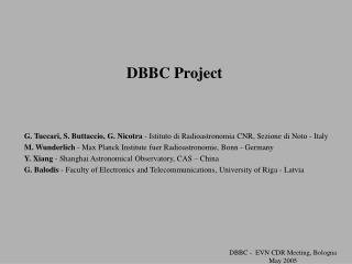
Gigabit Capability in the DBBC. G. Tuccari 1 , M. Wunderlich 2 , C. Manko 2 1 Istituto di Radioastronomia – INAF, Italy 2 Max Planck Institute fuer Radioastronomie, Germany. Summary.

E N D
Gigabit Capability in the DBBC G. Tuccari1, M. Wunderlich2, C. Manko2 1 Istituto di Radioastronomia – INAF, Italy 2 Max Planck Institute fuer Radioastronomie, Germany 7th e-VLBI Meeting, June 16-17, 2008 Shanghai
Summary The DBBC VLBI system disposes of a multi-gigabit link facility. The board performing such functionality is named FILA10G because the 10G network standard is applied. A description is given about the available functionalities that can be adopted for several connection types. Indeed it’s possible to join different part of the DBBC system with such fast link or produce data to be injected on an external network for e-VLBI purposes.
DBBC.2 7th e-VLBI Meeting, June 16-17, 2008 Shanghai
ADB2 • ADB2 board: - The board offers several operation modes with demultiplexing in two or four bus - Maximum sampling clock is 2.2 GHz, maximum signal frequency to be sampled is 3.5 GHz, 10-bit representation - A board ADB2 can feed as piggy-back element a FiLa10G, giving the possibility to place the sampling element in the receiver site, connecting with optical fibres the DBBC processing unit
ADB2 AD Demultiplexer Piggy-back connection
Core2 • Core2 board in the V5 version: - The board is compatible with ADB1 and ADB2 and support a minimal equivalent functionality of four Core1 with typical internal clock for matched elements up to 550 MHz - A piggy-back element can be adopted for additional functionality, like a memory bank for pulsar de-dispersion or other needs where a significant memory addition is to be adopted - The memory bank as p-b board is under construction - The Core2 pcb has an number of 40 equivalent layers and all the connections for signal transfer are differential, twisted, matched in delay and impedance between the pads of the dice and the pins of the bus connectors
Core2 Monitor No extrenal terminations Voltage regulators Piggy-back connection
Minimal version 1 ADB2 1 CORE2 Es. 1GHz IF bwd and 4 dbbc functionality or multiband (8 x 64 MHz fixed tuning)
FILA10G • FiLa10G Ethernet board: - Can be used as piggy-back board of any ADB2 sampler, to transmit and receive in the same time a data rate of 20 Gbps in + 20 Gbps out, additionally Ethernet connection 1-2-4 Gbps in fibre or copper - The bidirectional functionality (round-trip) can be required when a RFI mitigation is needed to be realised in a remote position with respect to the sampling and processing site - With the typical sampling frequency of 2.048 MHz and the full 10-bit data representation, a double optical fibre set meets the requirement - More transceivers are expected to be used, with the possibility to populate the board even with one transceiver only -One board can support the data tx-rx of 2xVSI connections as p-b element of a ADB2 or as stand alone element - The entire triangle connectivity HSI/HSIR --- VSI in/VSI out --- Optical Fibres is supported 7th e-VLBI Meeting, June 16-17, 2008 Shanghai
2xOF 10G FiLa10G Connectivity FiLa10G 1ch HSI 10bit 2.048GHz clk 2xVSI 64ch@128MHz FiLa10G Board Add 10G Connectivity Connectedto the ADB2 or to the VSI output connectors IN/OUT Triangle Connection CDR 2nd - Bologna
FILA10G 1HSIin+1HSIRout 1-2-4 Gbps 2VSIin+2VSIout 2 X 10Gbpsin+10Gbpsout 7th e-VLBI Meeting, June 16-17, 2008 Shanghai
FILA10G Prototype 7th e-VLBI Meeting, June 16-17, 2008 Shanghai
FILA10G Prototype 7th e-VLBI Meeting, June 16-17, 2008 Shanghai
Connection examples • ADB2 Tx --> ADB2 Rx • ADB2 Tx/Rx <--> ADB2 Rx ADB2 Tx FILA10G FILA10G ADB2 Rx ADB2 Tx/Rx FILA10G FILA10G ADB2 Rx Core2 7th e-VLBI Meeting, June 16-17, 2008 Shanghai
Connection examples • ADB2 Tx --> 10G • ADB2 Tx/Rx <--> 10G ADB2 Tx FILA10G 10G card PC ADB2 Tx/Rx FILA10G 10G card PC 7th e-VLBI Meeting, June 16-17, 2008 Shanghai
Connection examples • 2 x VSI --> MK5C • 2 x VSI --> MK5C & MK5B FILA10G MK5C 2xVSI FILA10G MK5C 2xVSI MK5B/B+ MK5B/B+ 7th e-VLBI Meeting, June 16-17, 2008 Shanghai
Connection examples • 2 x VSI --> Network • etc. FILA10G 1- 2 - 4 - 10 – 20 Gbps Network 2xVSI DBBC FILA10G 1- 2 - 4 -10 - 20 Gbps e-VLBI 7th e-VLBI Meeting, June 16-17, 2008 Shanghai
The End 7th e-VLBI Meeting, June 16-17, 2008 Shanghai