Download
1 / 33
350 likes | 558 Views
Design Features and Commissioning of Versatile Experiment Spherical Torus (VEST) at Seoul National University. K. J. Chung, Y. H. An, B. K. Jung, H. Y. Lee, C. Sung, Y.S. Na and Y. S. Hwang. Center for Advance Research in Fusion Reactor Engineering.

E N D
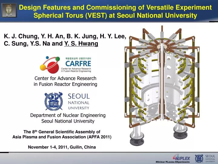
Design Features and Commissioning of Versatile Experiment Spherical Torus (VEST) at Seoul National University K. J. Chung, Y. H. An, B. K. Jung, H. Y. Lee, C. Sung, Y.S. Na and Y. S. Hwang Center for Advance Research in Fusion Reactor Engineering Department of Nuclear Engineering Seoul National University The 8th General Scientific Assembly of Asia Plasma and Fusion Association (APFA 2011) November 1-4, 2011, Guilin, China
Outline • Background & Motivation • Introduction to VEST Device • Design Features • Key Design Points with Operational Scenario • Research Plans • Commissioning • Vacuum Chamber and Center Stack • TF Coil System • PF Coil System • ECH Pre-ionization System • Diagnostics Plan • Port Assignment • Summary
Background & MotivationSpherical Torus (ST) Spherical Torus (ST) : Low aspect ratio (A<2) fusion device Large aspect ratio (Conventional Tokamak) Small aspect ratio (Spherical Torus) a R Advantages Weakness • High performance • : High β, High plasma current • Compactness Difficulty in start-up & sustainment due to the lack of space for solenoid Innovative start-up method is critical issue for ST! By developing new start-up and non-inductive current drive methods, ST can be a high performance fusion research device.
IntroductionVEST Status Man Power, but NO Power yet 23 June 2011 VEST successfully installed at SNU
IntroductionVEST(Versatile Experiment Spherical Torus) • Objectives • Basic research on a compact, high- ST (Spherical Torus) • with elongated chamber in partial solenoid configuration • Study on innovative partial solenoid start-up, divertor, etc • Specifications * Elongation : 3.3 assumed
Key Design Point Solenoid-Free Start-up • Plasma injection and merging is one approach for solenoid-free start-up Existing injection scenario • Compression-Merging method • : Use in-vessel PF coil’s swing (START, MAST) • Drawbacks of in-vessel PF coil • Impurity • Engineering problems • Double Null Merging (DNM) • : Use Outer PF coil swing (UTST) • Limitation : Hard to get equilibrium
Key Design Point Double Null Merging Start-up with Partial Solenoids Partial Solenoid Relatively smaller space for central solenoid in ST. Hard to supply sufficient magnetic flux. Breakdown by Partial Solenoid Solenoid Start-up • The most effective start-up method • High shaping and equilibrium ability • Hard to keep low aspect ratio • Difficult to apply to spherical torus Plasma Merging Partial Solenoid Operation • Inherits the merits of solenoid start-up • Possible to maintain low aspect ratio • Effective Start-up method • in Spherical Torus Breakdown by Partial Solenoid Partial Solenoid
Operational ScenarioLoop Voltage Calculation with Circuit Model • eddy currents are accounted in this model Eddy current @ Chamber wall Eddy current decay most slowly in thick cover wall Most severe at thick cover and wall close to PF2 Loop voltagedeceased by eddy current 38% Reduced
Operational Scenario Field Null Formation and Lloyd Condition • Lloyd condition • Field null formation with circuit model PF2, 3, 5, 8 Current Waveform Field Null Lloyd condition: Lloyd condition Max. at ~15 ms > 100 V/m for 0.7 ms * Induced eddy current at the chamber wall considered.
Operational Scenario Start-up Scenario utilizing Pressure Driven Current Breakdown by Partial Solenoid Pressure Driven Current by ECH Heating 2.45GHz 3kW ∙ • Trapped Particle Configuration at midplane. • Pressure driven current by ECH heating • Opposite direction to the main plasma current induced by partial solenoid. • But, it can be used as virtual coil for further optimization of null formation. 2.45GHz 6kW X Pressure driven current by ECH Trapped ParticleConfiguration 2.45GHz 3kW ∙ Breakdown by Partial Solenoid
Research TopicsSequential Tokamak Injection for Ramp-up PF #1 -0.044kA PF #1 -0.044kAt PF #1 -0.044kAt Small Plasma Solenoid 0A +40kAt 0A PF #2 -0.449kA PF #2 -0.45kAt PF #2 -0.449kAt PF #3 -1.833kA PF #3 -1.83kAt PF #3 -1.833kAt PF #4 -6.55kAt PF #4 -6.546kA PF #4 -6.546kAt Ip ~ 12kA Ip >12kA Ip ~ 12kA Solenoid charging Solenoid Swing Down Plasma injection +40kAt 0A Solenoid 0A Small Plasma Study on the feasibility of a sequential tokamak plasma injection method for maintaining plasma currents through partial solenoid operations.
Research TopicsEC/EBW H&CD • Use of ECRH is limited in ST device due to cutoff density. • However, Electron Bernstein Wave (EBW) heating through mode conversion is possible since EBW has no cutoff density. 7.5GHz ECR 5GHz ECR 2.45GHz FHM 5GHz SHM 7.5GHz THM HFS Launching O-mode cutoff 2.45GHz System under Preparation EBW heating and current drive will be studied LFS Launching 2.45GHz UHR Schematic of the EBW assisted plasma current start-up in MAST Various EC Resonance Layer in VEST [V.F. Shevchenko, et. al., Nucl. Fusion 50 (2010) 022004]
Research TopicsInnovative Divertor Concepts • Control of heat flux and neutron flux is one of important issue in fusion research • ST with high heat density and compactness is appropriate to heat flux study. • VEST with enough space for divertor and sufficient number of PF coils is suitable for divertor research Innovative divertor concepts such as super-X and snow-flake divertors will be investigated. 8 pairs of PF coils Enough Space for Divertor Single Null (Left) and Snowflake (Right) Configuration in TCV [F Piras et al,Plasma Phys. Control. Fusion 52 (2010) 124010 ]
Vacuum Chamber and Center StackOverall Dimensions of VEST Overall dimension of VEST Thickness of vacuum chamber wall PF3 PF4 PF2 ~ 1.1 m 15mm 17mm 13mm 15mm PF5 3.4mm 0.6 m 6mm PF6 ~ 2.7 m PF7 0.8 m PF8 1.2 m 15mm 5mm PF1 13mm 15mm PF9 0.6 m 2.8mm 6mm PF10
Vacuum Chamber and Center StackDesign and Fabrication of Vacuum Chamber Upper Chamber 6” Port 4” Port Main Chamber Middle Chamber 12” Port Center Stack Parts Center Stack 10” Port Rectangular Port Lower Chamber V/V: S/S 316L Center Stack and Bottom Chamber
Vacuum Chamber and Center StackDesign and Fabrication of Center Stack Nipples for water cooling Cu block is brazed “Section A-A” PF1 Coil 2.4 m ~268mm G-10 Block Partial Solenoid (PF2) Epoxy molded f87mm A A f165mm Center Stack Chamber Wall 87mm Thin Solenoid (PF1) TF Coils (24ea) Inner TF Coils Inner Pipe (PF1 Bobbin)
TF CoilDesign Parameters of TF Coil Strand Specification for TF Coils Structure of VEST TF coil
TF CoilTF Coil Power Supply: Battery Banks VEST TF Coil Power Supply Pneumatic Switch MC Switch Battery Bank • Designed to able to supply up to 8.3 kA • Based on commercial deep-cycle battery • 5 banks with 40 batteries for each bank • (Total 200 batteries are used to make 0.1 T) • Adv.: Cost effective and long flat-top • Disadv.: Always contain large energy VEST TF Coil R = 15 mΩ L = 1 mH Emergency Safety Breaker Fuse 8.3kA for 4s
Commissioning Battery-based TF Power Supply • TF coil current of 8.6 kA is achieved successfully by using 8 battery modules (Note: BT@R0 = 0.1 T for 8.3 kA TF coil current). • To minimize high current load on batteries during the turn-off, the sequential switch-off is adapted.
PF CoilOverall Features of Various PF Coils Long Solenoidfor plasma sustaining Null formation Vertical stability & Control of small plasma PF3 PF4 PF1 Null formation PF5 Equilibrium of small plasma PF2 PF6 Vertical stability & Control of small plasma PF7 PF8 Null formation PF9 Partial solenoid for plasma start-up Equilibrium of main plasma • Strand Size - PF1 & PF2: 3.5mm*15mm • - PF3 ~ 10 : 6.5mm*6.5mm (3.5ф hole) PF10 • Pancake design of PF 3~10 Pancake module : 6*2 strands 4*2 strands for PF #3 & #4 Role of each PF coil
PF CoilDesign Parameters for PF1 & PF2 Solenoid Coils PF2 (Upper partial solenoid) PF1 (Long solenoid) PF2 (Lower partial solenoid) Stress limit: Tensile strength of Cu ~ 70 MPa
CommissioningPF2 Coil Power Supply • Power Supply for PF2 Coils • Scheme: Double swing circuit • Switching: Thyristor with ferrite isolation • Control: Optical trigger SW2 SW1 SW3 PF2 coil C1 (10 mF) C2 (0.2 mF) C3 (50 mF) HV Relay Module SW2 Gate trigger Module Capacitor bank SW1 Thyristor Module SW3
Commissioning ECH Pre-ionization for VEST 3kW, 2.45GHz Magnetron Reducer WR340→WR284 WR284 Waveguide Breakdown by Partial Solenoid with ECH Pre-ionization • VEST Preionization • Upper & Lower Chamber • Two cost-effective homemade magnetron power supplies • (3kW, 2.45GHz) • Low field side launching • Main Chamber • Commercial microwave power supply (6kW, 2.45GHz ) • Low field side launching 2.45GHz 3kW WR340 Waveguide 6” port Vacuum Window ECH injection system for pre-ionization Merged Plasma 2.45GHz 6kW Magnetron 2.45GHz 3kW Breakdown by Partial Solenoid with ECH Pre-ionization
Preparation for Operation Port Assignment MM 11 : Pumping Duct MM12 : 7.5 GHz Klystron 2.45GHz ECH Power, 6kW UU1/MM1/LD1 : Halpha Monitoring UT1/ LB1 : ECH (Magnetron, 3kW) MM2 : NBI In MM10 : Vacuum BNC UU3 : Interferometry MM3 : Laser In (TS,LIF) UU9/LD9 : Vacuum BNC MM9 : Soft X-ray UU8 : GDC MM8 : Fast CCD LD8 : Pressure Guage UT4 : Piezoelectric valve MM4 : Detector for CXS UT7/LB7 : ECH (Power Supply) MM7 : Laser Out (TS,LIF) UU5/LD5 : Fast CCD MM5 : Laser Detector (TS,LIF) MM6 : NBI Dump Yellow color in future plan.
Summary • Summary • A new spherical torus named as VEST (Versatile Experiment Spherical Torus) has been built to be a low cost, compact, educational fusion research device at Seoul National University. • Operation scenarios with two partial solenoid coils are prepared by using a simple circuit model accounting eddy currents. • Various research plans such as double null merging start-up, sequential tokamak injection, innovative divertor concepts and non-inductive heating & current drive with EBW are considered. • Coil and heating powers with basic diagnostics are under preparation. • Discharge cleaning and breakdown-test are ongoing. • Fist plasma is coming soon !
Thank you for your attention ! VEST Installation Movie Clip
Thank you for your attention ! Collaboration is strongly Welcome !
Center for Advance Research in Fusion Reactor Engineering (CARFRE) • Lead the development ofkey technologies crucial for continuous and stable operation of fusion reactors • Develop analysis toolsand compile experimental database for fusion reactor design and systems integration • Foster well-trained fusion research personnel • Promote international collaborations in fusion research <Group 1> Fusion Reactor Systems Integration and Plasma Control Technologies <Group 2> Fusion Reactor Edge Plasma Technologies <Group 3> Advance Technologies of Fusion Energy Conversion System • Organization: 10 Projects with 16 Principal Researchers • from 5 Major Universities and 2 National Institutes • Funding: ~1M US$/yr for 6.5years(+ 3 years optional) 28
Phase 1 (Sep 2008- Feb 2012): Key Technology Development with Research Infrastructure Group1Fusion Reactor Systems Integration and Plasma Control Technologies Group2Fusion Reactor Edge Plasma Technologies • Blanket analysis model • Tritium behavior analysis • Edge plasma models • PFCs property tests • Analysis tool for the • integrated system • Core plasma models • 통합시스템 해석체계 • 노심 플라즈마 모델 Heat and particle flux,System integration data Neutron flux,System integration data Group3Advance Technologies of Fusion Energy Conversion System PFCs, BlanketHigh temp/Low activation material 29
Phase 2 (Sep 2013- Feb 2015):Integration of Key Technologies for Applications Group1Fusion Reactor Systems Integration and Plasma Control Technologies Group2Fusion Reactor Edge Plasma Technologies • Blanket analysis model • Tritium behavior analysis • Edge plasma models • PFCs property tests • Analysis tool for the • integrated system • Core plasma models • 통합시스템 해석체계 • 노심 플라즈마 모델 Heat and particle flux,System integration data Neutron flux,System integration data Group3Advance Technologies of Fusion Energy Conversion System PFCs, BlanketHigh temp/Low activation material 30
Research TopicsSequential Tokamak Plasma Injection Suppose that 12kA main plasma initiated by merging two 6kA plasmas ① ② ④ ③ ① : Solenoid charging-up phase (12kA main plasma sustaining) ② : Plasma current ramp-up by merging (ramp up from 12kA to 21kA) ③ : Solenoid charging-up phase (21kA main plasma sustaining) ④ : Plasma current ramp-up by merging (ramp up from 21kA to 30kA)
List of Research Topics for VEST • 1. Fusion Engineering • Plasma startup and ramp-up • Innovative divertor concept • PFC surface coating and material test • 2. Plasma Transport and Stability • Confinement scaling • Effect of SOL flow on plasma rotation • Alfven wave characteristics in spherical torus • Magnetic reconnection mechanism during merging phase • Bootstrap current in spherical torus • 3-D physics by internal coils like magnetic perturbations. • Asymmetric plasma characteristics in same magnetic flux surfaces • Transport & Stability studies during merging phase • Shaping effect on plasma including negative triangularity • Isotope effect as working gas • 3. Heating and Current Drive • ECH&CD including mode conversion • Synergetic effect among heating schemes • 4. Plasma-Wall Interactions • SOL physics • Dust