Download
1 / 18
190 likes | 350 Views
Ant Colony Optimization for Cell Routing in VLSI Chips. Shashank Hegde, Santosh Kelgeri. Design Flow Overview. Idea/Specifications. High Level Language Description. Synthesis & Placement. Routing. Chip Signoff. Manufacturing/Testing/Packaging. Design Flow Overview.

E N D
Ant Colony Optimization for Cell Routing in VLSI Chips Shashank Hegde, Santosh Kelgeri
Design Flow Overview Idea/Specifications High Level Language Description Synthesis & Placement Routing Chip Signoff Manufacturing/Testing/Packaging
Design Flow Overview Idea/Specifications High Level Language Description Synthesis & Placement Routing Chip Signoff Manufacturing/Testing/Packaging
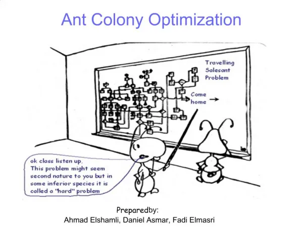
Billions of transistors… … how to connect them up?
Expected Routing 3 This connection has to take a detour as Manhattan path is not possible
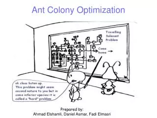
What’s the challenge ? • N-P hard in nature • Two nodes cannot always be connected by shortest path • Resources need to allocated to obtain a globally optimal solution • Cost based sequential routing suffers : High priority nets get priority and are assigned the resources first and gets progressively hard for the nets later in the order • Iterative in nature • Better method to tackle this issue? Heuristics
Ant Colony Optimization for Cell Routing in VLSI Chips
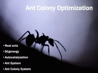
Ant Colony Optimization • Models real world ant behavior • Ants work collectively to find optimal solutions • Each ant explores the solution space for a solution • Deposit pheromones to guide future ants • Pheromone deposition is based on the quality of the solution found • After enough iterations, majority of the ants converge on the optimal solution
ACO for Routing • A different type of ant species is spawned for each connection • In each iteration the ants find paths to the destination • At the end of an iteration, the solution quality is evaluated • Pheromones are deposited on the edges to guide ants in future iterations
Solution quality evaluation • Shortest path found among all ants is the best solution • Results in maximum pheromone deposition • But, there can be contention • Edges in contention have negative effect on pheromone deposition • Bends need to be avoided as they are difficult to fabricate • Pheromone deposition is inversely proportional to the number of bends in the solution
Parallel ACO • Essentially a parallel algorithm • An iteration of each ant species is run in parallel • Every ant can also run in parallel • Solution evaluation of path found by an ant can also be done in parallel, but has to wait for all ants to find a path • Pheromones can be deposited in parallel, but can only be done after all solutions are evaluated
Parallel ACO AS1 AS2 AS3 Path finding Solution Evaluation Pheromone Deposition
Implementation & Evaluation • Shared memory model using CILK • Vary parameter weights of the evaluation function • Compare with standard algorithms
Problem Formulation and Underlying Assumptions • Routing possible only in orthogonal directions (Horizontal and Vertical). There is a minimum pitch (tracks) associated with two wires in the same direction. • As a result, routing can be treated as a grid graph – each edge corresponds to a track and components placed on nodes. • No two interconnects can share the same edge. • Even though real problems are formulated as hyper-graphs, we consider only two pin connections. Hyper-graphs can always be reduced to simple graphs. • Real designs has 8-9 layers, but can be abstracted away with 2 layers as we’re dealing with this project. Objective • Ideal solution: Assign edges/tracks for all nets in a manner that each one follows Manhattan path (L-shape) • Good solution: Assign edges/tracks such that the total distance of all nets is minimum • Better solution: Assign edges/tracks such that the deviation of nets with respect to their Manhattan distance is minimum (This is additional constraints for hypergraph, not simple graph)