Download
1 / 21
350 likes | 1.61k Views
SINGLE PHASE INDUCTION MOTOR SOFT START BY STEPPED DELAY OF REDUCING FIRING ANGLE. Submitted by:. Contents. Project overview Block diagram Power supply Induction Motor Soft start of IM Comparator Opto-isolator Schematic & Working of the project Advantages Applications Future scope

E N D
SINGLE PHASE INDUCTION MOTOR SOFT START BY STEPPED DELAY OF REDUCING FIRING ANGLE Submitted by:
Contents • Project overview • Block diagram • Power supply • Induction Motor • Soft start of IM • Comparator • Opto-isolator • Schematic & Working of the project • Advantages • Applications • Future scope • Conclusion
Project overview • These Solid State Switches are phase controlled in a similar manner to a light dimmer, in that they are turned on for a part of each cycle. • The average voltage is controlled by varying the conduction angle of the switches. • Increasing the conduction angle will increase the average output voltage. • Controlling the average output voltage by means of solid state switches has a number of advantages.
Contd.. • One of the major advantages being the vast improvement in efficiency relative to the primary resistance starter, due to its low on state voltage of the solid state switches.
Contd.. • The 230V AC supply is first stepped down to 12V AC using a step down transformer. • This is then converted to DC using bridge rectifier. • The AC ripples is filtered out by using a capacitor and given to the input pin of voltage regulator 7812. • At output pin of this regulator we get a constant 12V DC which is used for different ICs in this project.
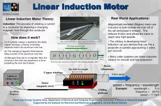
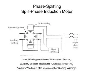
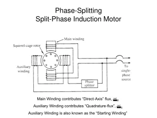
Induction Motor • The single-phase induction machine is the most frequently used motor for refrigerators, washing machines, clocks, drills, compressors, pumps, and so forth. • The single-phase motor stator has a laminated iron core with two windings arranged perpendicularly. • One is the main and • The other is the auxiliary winding or starting winding
Contd.. • This “single-phase” motors are truly two-phase machines. • The motor uses a squirrel cage rotor, which has a laminated iron core with slots. • Aluminum bars are molded on the slots and short-circuited at both ends with a ring.
Soft starter • A soft starter is another form of reduced voltage starter for A.C. induction motors. • The soft starter is similar to a primary resistance or primary reactance starter in that it is in series with the supply to the motor. • The current into the starter equals the current out. • The soft starter employs solid state devices to control the current flow and therefore the voltage applied to the motor. • Soft starters are connected in series with the line voltage applied to the motor, or can be connected inside the delta loop of a delta connected motor, controlling the voltage applied to each winding.
Contd.. • Voltage control is achieved by means of solid state A.C. switches in series with one or more phases. These switches comprise either: a. Triac b. diode & SCR c. Two SCRs
SCR • A Silicon Controlled Rectifier (or Semiconductor Controlled Rectifier) is a four layer solid state device that controls current flow • An SCR can be seen as a conventional rectifier controlled by a gate signal • It is a 4-layered 3-terminal device • When the gate to cathode voltage exceeds a certain threshold, the device turns 'on' and conducts current
Contd.. • The operation of a SCR can be understood in terms of a pair of tightly coupled Bipolar Junction Transistors • SCR has three states: • Reverse blocking mode, forward blocking mode, and forward conducting mode
Comparator • op amps & comparators look very similar • But a comparator gives a logic output indicating the relative potentials on its two inputs • An op amp amplifies the differential voltage between its two inputs – and is designed always to be used in closed-loop applications
Contd.. • Potential dividers are connected to the inverting and non inverting inputs of the op-amp to give some voltage at these terminals. • Supply voltage is given to +V and –V is connected to ground. • The output of this comparator will be logic high (i.e., supply voltage) if the non-inverting terminal input is greater than the inverting terminal input of the comparator. • If the inverting terminal input is greater than the non-inverting terminal input then the output of the comparator will be logic low (i.e., gnd).
Optocoupler • Opto coupler is a 6 pin IC. It is a combination of 1 LED and a diac. Pin 5 is not generally used and when light falls on the diac then it switches ON the diac.
Contd.. • When logic zero is given as input to the LED then the light doesn’t fall on diac so the diac is off means the current does not flow through the diac. • When logic 1 is given as input to the LED then light emitted by LED falls on diac so it starts conducting i.e., now there will be current flowing through the diac.
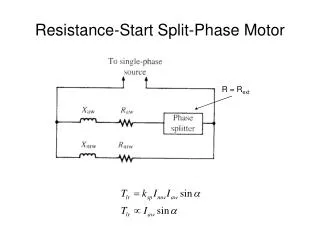
Working of project • To start the motor with low current, two SCR’S are connected back to base in each phase. • They are triggered slowly initially and gradually the triggering pulse is increased, so that motor gets high current after a time delay when windings are in the position of withstanding the high current. • To trigger the gates of SCRS the op-amps are used. • Op-amp is configured to get a level voltage that will initially be high and gradually fall to zero.