Download
1 / 12
830 likes | 2.3k Views
Capacitive Sensors. As noted earlier, the sensor traces can be any number of different shapes and sizes: Buttons, wheels, scroll-bar, joypad, and touchpad. Buttons. Capacitive Sensors. Slider. 8-way switch. Wheel. Capacitive Sensors. Keypad. Touchpad. Capacitive Sensors.

E N D
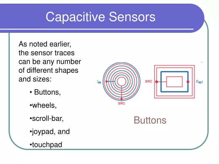
Capacitive Sensors • As noted earlier, the sensor traces can be any number of different shapes and sizes: • Buttons, • wheels, • scroll-bar, • joypad, and • touchpad Buttons
Capacitive Sensors Slider 8-way switch Wheel
Capacitive Sensors Keypad Touchpad
Capacitive Sensors • Capacitance sensors detect a change in capacitance when something or someone approaches or touches the sensor. The technique has been used in industrial applications for many years to measure liquid levels, humidity, and material composition. A newer application, coming into widespread use, is in human-to-machine interfaces. Mechanical buttons, switches, and jog wheels have long been used as the interface between the user and the machine. Because of their many drawbacks, however, interface designers have been increasingly looking for more reliable solutions
How does it work The goal is to develop a capacitive sensor that has the right response and meets ergonomic requirements. In some applications, the sensor may have to be small, resulting in small changes in capacitance levels upon user contact. www.zaoqiche.com/qczz/qcyy/ywlw/110946.as
Alignment of plates • Aligning of two plates on the basis of capacitive value: Capacitive value between electrodes represent , where A is changing as the two plates are moved for alignment. Therefore one could exploit this for making accurate alignment.
Fluid Pressure A and B being electrodes representing a capacitive value between two plates. While the area is changing due to pressure on B as diaphragm, therefore a change in d is experienced. Such change is proportional fluid pressure on this diaphragm. This as bridge out reading through moving coil meter could be calibrated for pressure measurement. A B
Linear Displacement • Capacitive value is dependant upon electrolyte of the fluid in the cylinder. While due to linear displacement of the piston the fluid matter is pushed out/pushed in, therefore causing change in Capacitance due to r:
Fluid Level Inner float is representing fluid level in the tank. Movement of the float is causing change in area under outer plates of the capacitance therefore could be exploited to measure the level.
Frequency • Capacitive transducer is used as part of active oscillator, where a change in frequency is reflected in terms of voltage for a meter scale to give frequency readings.
Fluid Pressure A diaphragm is pushed out as a result of fluid pressure, causing respective changes in capacitive values of C1and C2. Both of these capacitors are part of two legs of a Wheatstone Bridge therefore reading could be measured as voltage, scaled for fluid pressure
Linear Displacement The sensing shaft in a capacitive transducer changes the position of the dielectric between the capacitor's plates in the transduction element, or it changes the distance and area between the plates. A change of these three parameters leads to a change in capacitance, which is a measure of the quantity to be measured.Capacitive displacement transducers with variation in dielectric constant (a), gap between plates (b), and area of capacitor's plates (c).