Download
1 / 19
300 likes | 638 Views
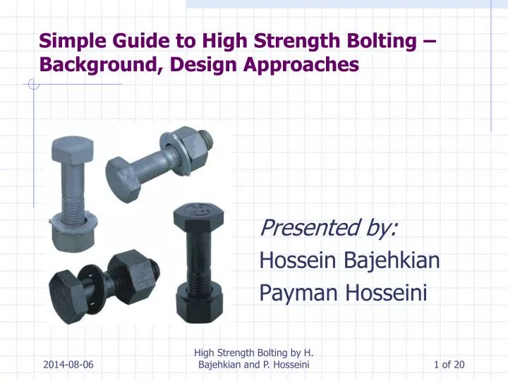
Simple Guide to High Strength Bolting – Background, Design Approaches. Presented by: Hossein Bajehkian Payman Hosseini. Outline. Rivets Bolts Different methods of Pre- tenstioning of High-strength Bolts Tension Behavior of Bolts and Prying Action Shear Behavior of Bolts

E N D
Simple Guide to High Strength Bolting – Background, Design Approaches Presented by: HosseinBajehkian PaymanHosseini High Strength Bolting by H. Bajehkian and P. Hosseini
Outline • Rivets • Bolts • Different methods of Pre-tenstioning of High-strength Bolts • Tension Behavior of Bolts and Prying Action • Shear Behavior of Bolts • Typical Shear Connections High Strength Bolting by H. Bajehkian and P. Hosseini
Rivets • ASTM A502 • More expensive to install than bolts • More man power • More equipment • Problematic when slip critical conditions are required as the amount of pretension depend on • Compactness of griped material • Initial temperature • Pretension is limited toultimate strength which is much lower than bolts High Strength Bolting by H. Bajehkian and P. Hosseini
Bolts • High-Strength Bolts • ASTM A325 • Min Tensile Strength • 830 Mpa for dia, up to 1 inch • 725 Mpa for larger dia • ASTM A490 • Min Tensile Strength 1030 Mpa • Max Tensile Strength 1168 Mpa • Main advantage is the ability to have large magnitudes of pretension . • Two Types of Bolts • Common • High-strength • Common Bolts • ASTM A307 • Min tensile strength 415 MPa • Used for general applications • Good for static loads • Cheap High Strength Bolting by H. Bajehkian and P. Hosseini
Pretension of High-Strength Bolts • Desired amount of pretension is 70% of bolt’s min specified tensile strength (2004 CSA Std.) • Snug-tight condition is adequate for many applications • Four methods of pretentioning • Turn-of-nut method • Calibrated wrench • Use of Tension-Control bolts • Use of direct tension indicators • Pretension is required • Cyclic Loading • Oversized or slotted holes • Shear connections under seismic load • Failure to achieve pretension can lead to unwanted displacement or fatigue-type failure • In seismic applications effectiveness of energy dissipation mechanism depends on preloading of the joint • Vibration loosening and loss of nut is prevented by adequate pretensioning High Strength Bolting by H. Bajehkian and P. Hosseini
Turn-of-nut Method • Pretension is achieved by turning the nut past the snug-tight condition • Strain controlled method • Amount of pretension depends on the friction between the bolt threads and nut • Amount of pretension is about 35% higher than minimum specified High Strength Bolting by H. Bajehkian and P. Hosseini
Calibrated Wrench Method • Tension controlled method • There is relationship between the applied torque and magnitude of pretension • Complex relationship depends on • Thread pitch • Thread angle • Friction coefficient between the nut and bolt • RCSC Specifications does not recognize the available formulas and tables to relate the torque to tension • Wrenches are calibrated on site using a representative sample of bolts that are being used High Strength Bolting by H. Bajehkian and P. Hosseini
Tension-control Bolts • Also known as Twist-off Bolts • ASTM F1852 • They meet the requirements of A325 but have special features • Pretension depends on • Bolt material strength • Diameter of annular groove • Thread conditions • Surface conditions at nut-washer interface • Min pretension achieved is likely to exceed the specified pretension by 13%. • Three advantages • Single person can perform the installation • Installation is quicker • Inspection is simple as the spline end of the bolt is twisted off High Strength Bolting by H. Bajehkian and P. Hosseini
Use of Direct Tension Indicators (DTIs) • ASTM F959 • Washer-type elements that have arch-shaped protrusion • Protrusions compress in response to tension force in the bolt • Tension force is determined by measuring the size of the gap • Deformation controlled method and friction related variables do not affect the pretension • Min pretension achieved is likely to exceed the specified pretension by 12%. High Strength Bolting by H. Bajehkian and P. Hosseini
Tension Behavior of Single Bolt • Tensile Strength of a single bolt depends on: • Ultimate Tensile Strength • Effective Area • Represented in S16-09 as: Where: • Ab is the nominal crosssectional area of the bolt and 0.75 factor accounts for the reduction in the threaded section • Fu is the ultimate tensile strength of the bolt • φb is the resistance factor for the bolts which is equal to 0.80 High Strength Bolting by H. Bajehkian and P. Hosseini
Tension Behavior of Group of Bolts • Bolts are normally pre-tensioned to their connected elements to provide slip resistance • The force in a pre-tensioned bolt can be calculated assuming equal deformation of bolt and plate until the separation of connected elements • The most important issue is prying action: • Occurs when the bolt force is amplified due to the deformation of connected elements • Depends on bolt deformation capacity. flange stiffness and location of bolts in the flange High Strength Bolting by H. Bajehkian and P. Hosseini
Shear Behavior of Single Bolts • Ultimate Shear Strength of bolts are closely related to: • Tensile Strength • Type of Test • Axial Load on the Fasteners (Tension or Compression) • Factors Affecting Shear Resistance of a Bolted Connection • Ultimate Shear Strength ~ 60% of Tensile Strength • Number of Shear planes and bolts • Shear Area S16-01 Shear Resistance Equation: High Strength Bolting by H. Bajehkian and P. Hosseini
Slip Condition in Bolts Loaded in Shear • To ensure low probability of slip during the life of structure • Joints shall not slip due to serviceability load • Used in connections subjected to stress reversals and fluctuations • Slip Load depends on: • ks= slip coefficient • m= number of slip planes • ΣT = Sum of bolt tensions S16-09 Slip Resistance Equation: • c1 is a coefficient that relates the specific initial tension and mean slip to a 5% probability of slip for bolts installed by the turn-of-the-nut method and depends on the type of bolt • 0.53nAbFu denotes the clamping force of the bolt in the S16-09 equation where: • 0.53 comprises of 0.70 factor which reflects that the amount of pretension need to be 70% of the ultimate tensile strength and 0.75 factor accounts for the reduction in area High Strength Bolting by H. Bajehkian and P. Hosseini
Shear Splices • Plates or parts of steel section connected to each other by series or rows of bolts • Variations include: lap joints, shingle joints, gusset plates • The shear plane is parallel to the longitudinal axis of the member • Reduction in ultimate capacity of the bolt due to uneven distribution of stresses of the bolts • Higher stresses at the ends of the plates and lower stresses in the middle High Strength Bolting by H. Bajehkian and P. Hosseini
Gusset Plate • Used to transfer the load from one member to the other when the longitudinal axis of two or more member are inclined with respect to each other • Insignificant out of plane bending • Classical Analysis Procedure: • Taking sections parallel and perpendicular to the chord of the truss • identifying the bolt forces that had been delivered to the gusset plate, and utilize these forces to calculate the shear, normal force, and moment at the cut section using beam theory High Strength Bolting by H. Bajehkian and P. Hosseini
Gusset Plate • Whitmore’s Analysis Approach. • maximum normal stress can be estimated by assuming that the member force was distributed uniformly over an effective area of plate material • This area was obtained by multiplying the thickness of the plate by an effective length which is obtained by constructing 30° lines from the outer fasteners to the bottom fasteners as shown. • Finite Element Method Analysis • Several models have been developed and analyzed the gusset plate in the elastic range and also predicted its behavior up to its ultimate strength • Whitmore’s conclusions were confirmed by the results of the analysis • Inaccuracy of the beam theory employed in the classical approach was also confirmed however it appeared to be more conservative. High Strength Bolting by H. Bajehkian and P. Hosseini
Eccentrically Loaded Joints • When the applied load results in a line of action passing outside the center of rotation of the fastener group. • Common examples: bracket-type connections, web splices in beams and girders, and standard beam connections High Strength Bolting by H. Bajehkian and P. Hosseini
Eccentrically Loaded Joints • Design Procedure: • Three equations of equilibrium must be employed to determine the coordinates of the instantaneous center of rotation and the maximum value of the load that results in slip of the connection. • A trial centre of rotation is selected and iterated until the three above equations of equilibrium are satisfied. • Design Assumptions: • the connection rotates about an instantaneous center of rotation. • Maximum slip resistance of all fasteners is reached at slip load. • The slip resistance of each fastener can be represented by a force at the center of the bolt acting perpendicularly to the radius of rotation High Strength Bolting by H. Bajehkian and P. Hosseini
Questions High Strength Bolting by H. Bajehkian and P. Hosseini