Download

1 / 42
420 likes | 549 Views
Supporting Ethernet in OBS networks. Sami Sheeshia and Chunming Qiao Department of computer science and engineering State University of New York at Buffalo Jeffrey U.J.Liu Computer and Communications Research Lab Industrial Technology Research Institute, Taiwan

E N D
Supporting Ethernet in OBS networks Sami Sheeshia and Chunming Qiao Department of computer science and engineering State University of New York at Buffalo Jeffrey U.J.Liu Computer and Communications Research Lab Industrial Technology Research Institute, Taiwan 2002 Journal of Optical Computing
Overview • Abstract • Introduction - various standards to enhance Ethernet • 10GbE over SONET - disadvantages and quantifying its inefficiencies • Ethernet over OBS - presenting a viable alterative which avoids the shortcomings of SONET. • Ethernet over OBS specific integration issues- - such as OBS burst size - Multiprotocol Label Switching (MPLS) issues
Abstract • The paper introduces the likely role that OBS will play in the development of 10-Gbit Ethernet MAN. • SONET (Synchronous optical networking) is being proposed for the same but its synchronous time-division multiplexing (TDM) is inefficient for transporting bursty traffic of the Ethernet. • The author claims that OBS provides a better sharing of network resources and when coupled with generalized multiprotocol label switching (GMPLS) provides a robust Ethernet service.
Introduction • Recently network providers face new challenges at the MAN level due to the increased user requirements. • Tremendous pressure to support broadband access and high speed WAN at low cost. • So the above factors demands a flexible, proven MAN architecture combined with multi-vendor compatible implementations. • 10GbE promises to play an important role, offering good speed, end-to-end protocol consistency for providers and users in a cost effective manner. • 10GbE can operate over long link spans(40 km) and other transport layers such as SONET and DWDM.
Intro…SONET • Historically, wide-area connectivity is been provided by SONET which were built to carry voice traffic. • But it is not optimized for the bursty nature of the present time data traffic and is not able to scale itself to support the rapid growth of internet in a cost-effective manner (requires ADMs, hubs etc). • Gigabit Ethernet has been popular in LAN and the MAN , however, Ethernet by itself cannot be considered to be a carrier class protocol as it does not provide what SONET guarantees. • Standards such as Ethernet over WDM, resilient packet ring (RPR), packet over SONET (PoS) have been developed with carrier-grade qualities.
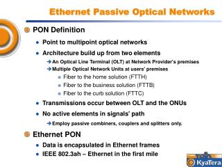
Intro..1.Ethernet over WDM • This provides a long haul connectivity(40 km) between two Ethernet switches. • Point-point connections are done manually or via multiprotocol lambda switching. Disadvantage: • Total number of circuits that can be provisioned are limited. • No traffic grooming or aggregation can be done.
Intro…2. Resilient packet ring (RPR) • Combines the advantages of Ethernet and SONET to give traditional carrier class features. • Has good MAC switching capabilities providing core fiber and ring operation. • Controlled bandwidth allocation, 50-ms service restoration, bounded delay and jitters etc. • Though RPR in conjunction with SONET and Ethernet can provide highly efficient MAN, carriers have opted to improve SONET transport instead.
Intro…3.Packet over SONET (PoS) • PoS is a communication protocol for transmitting packets over SONET. • PoS supports the sending of IP packets over WAN. Disadvantage: • It aggregates and encapsulates IP datagrams in Point-to-Point protocol (PPP) without any differentiation among different packet flows. • So, lacks multicast and QoS capabilities.
Intro…Next-generation SONET • Provides better bandwidth granularity than SONET and POS. • Virtual Concatenation (VC) technique allows a better match between Ethernet data rates and SONET line rate improving circuit use. • GFP is proposed to adapt multiservices to the SONET by a uniform mapping of Ethernet frames and client signals. • LCAS provides bandwidth-on-demand capabilities. Disadvantage • Does not address issues associated with using circuit-switching technology for data traffic.
A new proposal • Since the standards mentioned either lack end-to-end optical transparency or do not offer efficient use of core resources, OBS technology is taken advantage of to transmit Ethernet frames over WDM links. • The author explains this provides a scalable and data optimized alternative to SONET-based connectivity.
Ethernet over SONET(EoS) • SONET was designed primarily for voice applications and is based on circuit oriented technology. • Dual ring and equipment topology enables SONET to implement fast protection mechanisms. • 10GbE physical layer is compatible with SONET. ( OC-192 link speed, use of SONET framing). • Costly aspects like TDM support, performance and management functions have been avoided.
Disadvantages of using SONET rings for data transport: Basically SONETs point-to-point design, circuit switch applications give rise to its limitations.
1.Fixed circuits • SONET provisions point-to-point circuit between ring nodes => allocated a fixed amount of bandwidth. • In Fig.1(a) each node in the ring is allocated only one quarter of the total bandwidth. • Thus a limit is put on the maximum data burst traffic rates and increases the queuing delay. • To create a logical mesh as in Fig.1(b) requires N*(N-1) circuits which is time consuming and also waste ring bandwidth.
2.Muticast Traffic • Layer 2 muticast requires each source to allocate a separate circuit for each destination. • Thus, a mesh has to be created in which separate copies of the packet are sent to each destination. • Obviously, result multiple copies traveling around the ring, wasting bandwidth.
3.Wasted Protection Bandwidth • 50% of ring bandwidth and equipment is reserved for protection. • SONET does not give the provider the choice of when and how much bandwidth to reserve for protection. • Thus SONET does not provide protection in a cost-effective manner.
4.Added Overhead • SONET overhead (TDM capabilities, physical layer, management functions) for STS-192c frames resulting from the transportation of 10GbE frames over circuits built from SONET links is 3.7%. • But , at low traffic loads, efficiency worsens as large bursts of Ethernet frames are delivered in a fraction of SONET time slot. • Carrying increasing data traffic over manually provisioned circuit-switched networks makes it difficult to develop new services thus increasing cost.
Ethernet-over-SONET Efficiency Due to the burstiness and variable frame size of Ethernet traffic there is inefficiency in SONET framing. Efficiency of EoS is given by ηEoS = ηSONET ∙ ηPE (1) where ηPEpacking efficiency of Ethernet frames into SONET payload (SPE).
g - interarrival gaps • r - unused remainder (due to low traffic load, size of incoming frame >>remainder in time slot) • Let the Ethernet frame size be modeled with an exponential distribution with parameter λ frame/Byte.
The packing efficiency of the Ethernet frames into a SONET Tspe is given by Where M- maximum number of Ethernet frames that SPE can hold. B –size of the burst. Y – Sum of the first frame to the last frame. • Due to the bursty nature, the time intervals (g) >>>Tspe • Thus as g varies , ηPE becomes proportional to the offered load. (2)
Ethernet over OBS • MPλS – Lack of statistical multiplexing, leads to poor flexibility. • Recent arrival of optical cross connects (OXC) can be used to extend 10GbE over long distances- point to point permanent resource reservation-no longer shared among different 10GbE. • OBS is a new technology that exploits the large bandwidths of DWDM by avoiding electronic processing of optical packets. • No O-E-O conversions in OBS. • Burst- basic data block, collection of data frames with same destination address and QoS parameters.
EoS… • Optical burst is switched by a predetermined path by a control packet. • Improves backbone efficiency and offers excellent scalability.
EOS… The GMPLS labels are used to identify the destination edge switch and are mapped to available wavelengths at each OBS switch. 1.Switched paths: • LOBS – do not reserve the resources permanently • LOBS are set up dynamically to support required QoS and torn down once burst are transmitted. • Bandwidth allocated dynamically-burst by burst basis.
2. Peer-to-Peer Networking: • GMPLS extends WAN connectivity into the MAN-simplifies interface • Complex optical UNI interfaces not required. 3. Multicast traffic: • OBS provides multicast at WDM layer using light-splitting techniques-require additional hardware-complicate switch controls • GMPLS-based multicast provides simplification and scalability at no cost.
4.Protection and Restoration: • GMPLS fast reroute mechanism can be used to provide protection and restoration by automatically rerouting traffic on an alternate LOBS. • Accomplishes by precomputing number of LOBS paths at the same time the primary LOBS paths are established. • Integrating 10GbE over GMPLS enabled OBS requires specific details to burst size and GMPLS extensions.
Ethernet-over-OBS efficiency • OBS efficiency depends on the fraction of time the reserved bandwidth along a LOBS path is used by the burst . ts- time at which the bandwidth reservation starts T- burst time (burst size L/output data rate bo) To - offset time (3)
End-to-end queuing delay depends whether fixed or variable size bursts are used. • Fixed size burst allows paths to be set up as the burst is being assembled. • In the fixed size the data burst encounters no edge delay as long as the offset time = time taken to assemble the burst. • In the variable-size, control packet can only be sent after entire burst is assembled –minimum edge delay is To.
Ethernet-over-OBS Burst Size • For better efficiency, the OBS burst must be >>To-ts but not so large to cause significant queuing delays. • High bandwidth, full-duplex operation requires a flow control mechanism: 10GbE source and destination exchange flow control packets- to prevent data loss, throttle frame transmission rate. • Flow-control packets are typically 64 bytes, not assembled into bursts since it affects efficiency. • Elasticity of OBS burst unlike SONET fixed frame slot size allows it to adapt to the bursty nature of Ethernet. • Ethernet adaptor requires a minimum IFG between 2 successive frames; at 10GbE IFG ~9.6ns or 12 Bytes. • IFG provides receiving station time to update counters, check CRC of previous frame, mange the buffers.
Two ways to implement IFG:- • Insert the 12 Byte spacing at the 10GbE receiving interface - places new requirements on the processing at the destination switch to seek the start of each frame. • Incorporate the IFG within the burst - maintains the integrity of Ethernet transmission at the expense of wasted bandwidth within each burst. Since the IFG, preamble, frame check sequence (FCS) constitute a large overhead for the 1500 Byte Ethernet frame, 9000 Byte frames can be used to improve efficiency. For e.g.. 155,520-Byte(SONET slot) carrying 1500 Byte frames incurs 1% overhead whereas 9000-Byte frame requires fewer IFG, preamble resulting in 0.1%, a reduction of ten fold.
Performance comparison of EoS and EoB under different traffic conditions. EoB, Tg=1% EoS EoS EoB, Tg=5% EoB, Tg=1% Ti : burst aggregation time
Ethernet-overMPLS issues What is Multi-protocol Label Switching (MPLS) ? • A data mechanism to provide a unified service for both circuit-based clients and packet-switching clients. • Supports various network technologies like ATM, IP etc. • MPLS sets up label-switched paths (LSP) for packets , thus saving time for a LSR (router) to look up the next node for forwarding the packet to. • Does not have common control and traffic engineering for wavelength , TDM and fiber switching. Forwarding Equivalence class (FEC) Set of packets with similar characteristics is forwarded the same way.
IP 1 9 IP 2 9 IP 1 5 IP 3 9 IP 2 5 IP 3 7 IP 3 2 : LSR (Label Switch Router) : LER (Label Edge Router) MPLS network IP 2 B Working of a Label Switched Path IP 1 3 IP 2 3 C IP 1 IP 3 A IP 2 IP 3
Generalized Multi-protocol Label Switching (GMPLS) • Extends the MPLS functionality for TDM (labels-time slots) and FDM (labels= electromagnetic frequency of light waves). • Ethernet tunnels provisioned dynamically to create wide-area- VLANs. • Peer-to-peer networking where CPE is part of the MPLS cloud. • Establishes space division multiplexed paths where labels indicate the position of the data. • Establishes common control plane between IP service management and optical layers.
VLL : Virtual Leased Lines or Ethernet tunnels. ∙ CPE : Customer Premise Equipment. ∙PE : Provider’s Edge switch. ∙ VLAN (Virtual LAN) : a group of end-stations on multiple LAN segments and can communicate as if they were on a single LAN.
CPE exchanges tables with the provider’s edge (PE) switches using GMPLS signaling. • Ethernet frame arriving at the CPE from local LANS carry the original Ethernet fields and 802.1p/q headers (p- covers traffic class expediting and dynamic multicast filtering part of MAC bridges, q-defines services provided in Virtual LANs). • Frame is mapped to a FEC. FEC lookup yields the outgoing port and virtual circuit (VC) label, which is added to the frame and forwarded on the outgoing port toward PE switch.
The PE switch maps the Ethernet frame into an OBS burst and provides the required signaling by GMPLS label assignment in one of the following two addressing schemes, 1. Flat assignment scheme: • PE constructs a label forwarding base as shown below. • Like CPE label assignment , each label designates a unique LAN-MAC-FEC, one for each frame. • Only provides simple point to point connection. • Increases amount of labels and signaling.
2. Hierarchical assignment scheme: • Here each VLAN is assigned one VLL or LOBS label as shown in below. • So labels with same LOBS label aggregated in to the same burst. • Allows easy rerouting of VLAN traffic in event of failure. • Additional processing overhead.
PE looks up the incoming label, determines the VLAN, adds a LOBS label as shown below. • Frames with same LOBS label are aggregated into the same burst.
EoB path protection and restoration 1. At WDM level: At optical layer, schemes match that of SONET but inflexible, subjects of current research. 2. At Ethernet level: • Spanning Tree Protocol (STP ) is used to provide redundant paths. • Long convergence time not suitable =>LOBS constantly setup and torn down. 3. At GMPLS level: • Head end - when path fails, OBS switch signals head-end switch to use a backup LOBS path. • Local reroute – makes a local decision to redirect the burst.
Timely detour path is needed. • So, preestablished paths is essential in burst traffic. • Shortest reroute time =>decision made as close to the failure point. • Since it takes time to inform the head node, local reroute mechanism is preferred. • Impossible to predict where failure may occur. • Every switch and link along the path is protected, detour paths setup dynamically at the same time primary paths are set up.
Local reroute requires establishing (N-1) detour paths as shown. where N- number of OBS switches that the LOBS traverses.
Conclusion • Extending Ethernet services over OBS provides better scalability and bandwidth efficiency than with SONET. • SONET is limited by its TDM nature and by MPλS which does not provide statistical multiplexing. • As DWDM evolves more and more wavelength will be supported on each fiber. • Ethernet is best for LAN-MAN connectivity. • OBS provides efficient sharing of backbone resources. • GMPLS provides standard control mechanism to bridge distant MANs, provides protection with no permanent reservation of resources. • Providers improve their revenue stream and consumers reduce their network operational cost.