Download
1 / 10

E N D
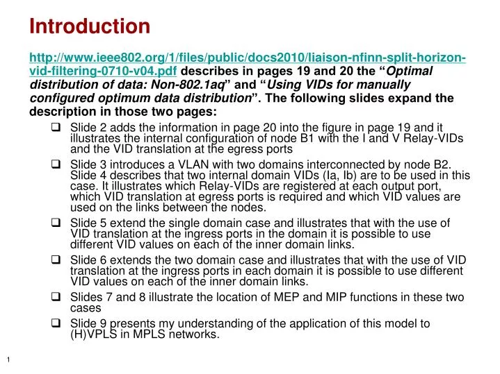
Introduction • http://www.ieee802.org/1/files/public/docs2010/liaison-nfinn-split-horizon-vid-filtering-0710-v04.pdf describes in pages 19 and 20 the “Optimal distribution of data: Non-802.1aq” and “Using VIDs for manually configured optimum data distribution”. The following slides expand the description in those two pages: • Slide 2 adds the information in page 20 into the figure in page 19 and it illustrates the internal configuration of node B1 with the I and V Relay-VIDs and the VID translation at the egress ports • Slide 3 introduces a VLAN with two domains interconnected by node B2. Slide 4 describes that two internal domain VIDs (Ia, Ib) are to be used in this case. It illustrates which Relay-VIDs are registered at each output port, which VID translation at egress ports is required and which VID values are used on the links between the nodes. • Slide 5 extend the single domain case and illustrates that with the use of VID translation at the ingress ports in the domain it is possible to use different VID values on each of the inner domain links. • Slide 6 extends the two domain case and illustrates that with the use of VID translation at the ingress ports in each domain it is possible to use different VID values on each of the inner domain links. • Slides 7 and 8 illustrate the location of MEP and MIP functions in these two cases • Slide 9 presents my understanding of the application of this model to (H)VPLS in MPLS networks.
V I V V I I E-LAN (I) C11 P11 B1 C12 I VID Translation at egress port P10 P13 P12 B3 P31 P30 I C3 P32 B1 V P21 P11 P23 B2 P20 I C2 VLAN has common VID value ‘I’ on the inner links B1-B2, B2-B3 and B3-B1 P10 C11 V V SVL V V I I IV V,I I B1 VI C12 VI V V,I V P13 IV I V IV B3 V V,I V P12 I I C3 IV V I VI V IV V B2 V V,I C2 VI VLAN has 2 Relay-VID values ‘I’ and ‘V’ which operate in SVL mode VI X: External VID XY, YX: Relay-VID X to VID Y Translation at egress port SVL: Shared VLAN Learning X: Internal Relay-VID
E-LAN (II) C11 P11 B1 C12 P10 P13 P12 B3 P31 P30 C3 P32 P21 P23 B2 P20 C2 VLAN has two domains with a full mesh of links P24 P25 P42 P52 P55 P40 B4 P45 P54 B5 C4 C52 P50 C51
Ia Ia V Ib V Ia Ib Ia V Ia V Ib V V Ib Ib Ia Ia Ib Ib E-LAN (II) C11 VLAN has common VID value ‘Ia’ on the inner links B1-B2, B2-B3 and B3-B1 V IV V,I VLAN in Node B2 has 3 Relay-VID values ‘Ia’, ‘Ib’ and ‘V’ which operate in SVL mode B1 VIa C12 VIa V V,Ia V Ia IaV V IaV B3 V V,Ia V C3 Ia IaV V V,IbIa V,Ib Ia IaV Ia V,Ib B2 B2 V V,Ia,Ib P21 C2 V,IbIa VIa,Ib V,Ib V,Ib IbV,Ia V,IaIb VLAN has common VID value ‘Ib’ on the inner links B2-B4, B4-B5 and B5-B2 SVL Ib Ib P20 Ia V V IbV VIb V V P23 Ia V V Ib V V,Ib B4 V B5 V,Ib C4 C52 VIb VIb IbV IbV Ib V,Ib IbV V VID Translation at egress port P24 C51 Ib Ib P25 X: External VID XY, YX: Relay-VID X to VID Y Translation at egress port SVL: Shared VLAN Learning X: Internal Relay-VID
V I V I V I R R E-LAN (III) C11 P11 B1 C12 Q P10 P13 P12 B3 P31 P30 P C3 P32 B1 V P21 P11 P23 R B2 P20 C2 P10 VLAN has different VID values ‘P’, ‘Q’ and ‘R’ on the inner links B1-B2, B2-B3 and B3-B1 C11 V V SVL V I V Q IV V,I I IQ VQ Q Q B1 VI C12 QI QV V V,I V P13 PI PV Q V B3 V V,I V P12 R P C3 IV IP VP V R RI RV V V B2 V V,I C2 IR VR VI VID Translation at ingress port VID Translation at egress port XY, YX: VID Y to Relay-VID X Translation at ingress port X: External VID SVL: Shared VLAN Learning X: Internal Relay-VID XY, YX: Relay-VID X to VID Y Translation at egress port
P P P Ia Ib V V R Ia Ib R R V Ia V Ib V V K L Ia Ia Ia Ib K K L L E-LAN (IV) VLAN has different VID values ‘P’, ‘Q’ and ‘R’ on the inner links B1-B2, B2-B3 and B3-B1 C11 V IV V,I IQ VQ B1 VI C12 QI QV V V,I V Q V PI PV B3 V V,I V P C3 IaP V,IbP IV V R V,Ib RI RV P V,Ib B2 B2 V V,Ia,Ib IaR V,IbR P21 C2 VIa,Ib VLAN has different VID values ‘K’, ‘L’ and ‘M’ on the inner links B2-B4, B4-B5 and B5-B2 V,Ib KIb KV,Ia IbL V,IaL V,Ib SVL K L P20 R V V LV VK V V P23 Ia M V V V V,I B4 V B5 V,I C4 C52 VI VM MV IV Ib V,I IV VID Translation at egress port V P24 C51 VID Translation at ingress port K L P25 XY, YX: VID Y to Relay-VID X Translation at ingress port X: External VID XY, YX: Relay-VID X to VID Y Translation at egress port SVL: Shared VLAN Learning X: Internal Relay-VID
V I Ia Ia Ib V V I V Ia Ib Ia I V V R R Ia V Ib V V Ib Ib Ia Ia Ib Ib MEPs and MIPs in these E-LAN cases • Looking at the models of Nodes B1 and B2 I am wondering where we have to place the MEP and MIP functions • Most logical location of the MEP and MIP functions is at the edge of the yellow ellipses; this minimizes the number of MEP and MIP instances to one UP MEP+MIP+DOWM MEP set per port Ia B2 P21 B1 V P11 SVL P20 P10 Ia V V V V SVL P23 Ia I V Ib Q I Q Q P13 P24 P12 R Ib Ib P25
V I B1 V P11 P P P V Ia Ib V I P10 V R V V Ia Ib R R SVL V I V R R Ia I V Q V Ib I V V Q Q L K Ib Ia Ia Ia P13 K L L K P12 R MEPs and MIPs in these E-LAN cases • Same two nodes, now with VID Translation at some of the ingress ports P B2 P21 V SVL P20 R V V V P23 Ia Ib Q P24 R K L P25
E-LAN in MPLS (VPLS, HVPLS) • Same model can be deployed for E-LAN support in MPLS; i.e. VPLS and HVPLS • External VID is to be replaced by PW label, and VLAN Tag is to be replaced by PW Label Stack Entry header • PW label values might be different in the two directions • For such case the PWlabel-to-RelayVID and RelayVID-to-PWlabel translations will use the different PW label values • Relay-VID is represented by means of a VSI • n VSIs (n≥2) are part of a “Shared VSI Learning” (SVL) group
E-Tree • To be added in v02