Download
1 / 6
60 likes | 82 Views
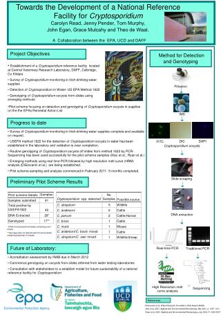
Detecting road lane is one of the key processes in vision based driving assistance system and autonomous vehicle system. The main purpose of the lane detection process is to estimate car position relative to the lane so that it can provide a warning to the driver if the car starts departing the lane. This process is useful not only to enhance safe driving but also in self driving car system. A novel approach to lane detection method using image processing techniques is presented in this research. The method minimizes the complexity of computation by the use of prior knowledge of color, intensity and the shape of the lane marks. By using prior knowledge, the detection process requires only two different analyses which are pixel intensity analysis and color component analysis. The method starts with searching a strong pair of edges along the horizontal line of road image. Once the strong edge is detected the process continues with color analysis on pixels that lie between the edges to check whether the pixels belong to a lane or not. The process is repeated for different positions of horizontal lines covering the road image. The method was successfully tested on selected 20 road images collected from internet. Ery M. Rizaldy | J. M. Nursherida | Abdul Rahim Sadiq Batcha "Reduced Dimension Lane Detection Method" Published in International Journal of Trend in Scientific Research and Development (ijtsrd), ISSN: 2456-6470, Special Issue | International Conference on Advanced Engineering and Information Technology , November 2018, URL: https://www.ijtsrd.com/papers/ijtsrd19136.pdf Paper URL: https://www.ijtsrd.com/engineering/civil-engineering/19136/reduced-dimension-lane-detection-method/ery-m-rizaldy<br>

E N D
International Journal of Trend in Scientific Research and International Conference on Advanced Engineering and Information Technology (ICAEIT-2017) Reduced Dimension Lane Detection Method Reduced Dimension Lane Detection Method International Journal of Trend in Scientific Research and Development (IJTSRD) International Conference on Advanced Engineering and Information Technology ISSN No: 2456 - 6470 | www.ijtsrd.com | Special Issue International Conference on Advanced Engineering ISSN No: 2456 Special Issue Publication Reduced Dimension Lane Detection Method Ery M. Rizaldy1, J. M. Nursherida 1Faculty of Engineering and Technology, 2School of Electrical, Electronic and Mechanical Engineering and Information Technology, ITP School of Electrical, Electronic and Mechanical Engineering and Information Technology, ITP School of Electrical, Electronic and Mechanical Engineering and Information Technology, ITP J. M. Nursherida2, Abdul Rahim Sadiq Batcha Engineering and Technology, Linton University College, Negeri Sembilan, Abdul Rahim Sadiq Batcha1 rsity College, Negeri Sembilan, Malaysia ABSTRACT Detecting road lane is one of the key processes in vision-based driving assistance autonomous vehicle system. The main purpose of the lane detection process is to estimate car position relative to the lane so that it can provide a warning to the driver if the car starts departing the lane. This process is useful not only to enhance safe driving but also in self-driving car system. A novel approach to lane detection method using image processing techniques is presented in this research. The method minimizes the complexity of computation by the use of prior knowledge of color, intensity and the shape of the lane marks. By using prior knowledge, the detection process requires only two different analyses which are pixel intensity analysis and color component analysis. The method starts with searching a strong pair of edges along the horizontal line of road image. Once the strong edge is detected the process continues with color analysis on pixels that lie between the edges to check whether the pixels belong to a lane or not. The process is repeated for different positions of horizontal lines covering the road image. The method was successfully tested on selected 20 road images collected from internet. Keywords: Feature Extraction, Lane Mark, Edge Detection, Autonomous Car. 1.INTRODUCTION With the advance of information technology, the use of image processing techniques for advanced driving system has attracted a good number of researchers. One of the earliest comprehensive studies of driver assistance system was presented by Mathias et al in 2007[14]. The report presented complete hardware and software requirement for advanced driver and software requirement for advanced driver assistance system. In October 2013, a researcher named Yenikaya presented the importance of lane marks detection [5]. This article provides a comprehensive review of vision systems. Yinghua He et al investigate an algorithm that has two modules: boundaries are based on the intensity image, and road areas are subsequently detected based on the full [9]. The combination of these modules can overcome the basic problems due to the inaccuracies in edge detection based on the intensity to the computational complexity of segmentation algorithms based on color images. Experimental results on real road scenes have substantiated the effectiveness of the proposed method. He et al proposed a color-based method for the non road (no lane marking) but the analysis causes computational burden [9]. Tu et al use Hough Transform techniques to extract lane marks from road images. This method requires an analysis of all images pixel and can only detect straight lane marks. For a better approach proposed Line parabolic model [4]. In 2009, a research team led by Lan et al developed a SmartLDWS method to detect lane mainly for smart phone usage. In 2014, Li et al investigated a novel real- time optimal-drivable-region and lane de system for autonomous driving based on the light detection and ranging (LIDAR) and vision data. The system uses a multisensory scheme to cover the most drivable areas in front of a successfully handles both structured and unst roads. The research team also proposed a multi method to handle the problem in producing reliable results [1]. lane is one of the key processes in driving assistance autonomous vehicle system. The main purpose of the lane detection process is to estimate car position relative to the lane so that it can provide a warning to car starts departing the lane. This process is useful not only to enhance safe driving but driving car system. A novel approach to lane detection method using image processing techniques is presented in this research. The method complexity of computation by the use of prior knowledge of color, intensity and the shape of the lane marks. By using prior knowledge, the detection process requires only two different analyses which are pixel intensity analysis and color is. The method starts with searching a strong pair of edges along the horizontal line of road image. Once the strong edge is detected the process continues with color analysis on pixels that lie between the edges to check whether the pixels belong e or not. The process is repeated for different positions of horizontal lines covering the road image. The method was successfully tested on selected 20 assistance system. In October 2013, a researcher presented the importance of lane marks detection [5]. This article provides a comprehensive review of vision-based road detection systems. Yinghua He et al investigate an algorithm modules: boundaries are first estimated y image, and road areas are subsequently detected based on the full-color image [9]. The combination of these modules can overcome the basic problems due to the inaccuracies in edge intensity image alone and due complexity of segmentation algorithms based on color images. Experimental results on real road scenes have substantiated the effectiveness of the proposed method. He et al based method for the non-structured road (no lane marking) but the inclusion of color analysis causes computational burden [9]. Tu et al use Hough Transform techniques to extract lane marks from road images. This method requires an analysis of all images pixel and can only detect straight lane marks. For a better approach, Jung and Kelber proposed Line parabolic model [4]. based system system and and In 2009, a research team led by Lan et al developed a SmartLDWS method to detect lane mainly for smart- phone usage. In 2014, Li et al investigated a novel Feature Extraction, Lane Mark, Edge region and lane detection autonomous driving based on the fusion of light detection and ranging (LIDAR) and vision data. The system uses a multisensory scheme to cover the With the advance of information technology, the use of image processing techniques for advanced driving system has attracted a good number of researchers. One of the earliest comprehensive studies of driver as presented by Mathias et al in 2007[14]. The report presented complete hardware front of a vehicle and successfully handles both structured and unstructured roads. The research team also proposed a multi-sensor method to handle the problem in producing reliable @ IJTSRD | Available Online @ www.ijtsrd.com | Special Issue Publication | November 2018 @ IJTSRD | Available Online @ www.ijtsrd.com | Special Issue Publication | November 2018 @ IJTSRD | Available Online @ www.ijtsrd.com | Special Issue Publication | November 2018 P - 191
International Journal of Trend in Scientific Research and Development (IJTSRD) | ISSN: 2456-647 In 2012, a research team led by Liu Xin investigated a new vision-based long-distance lane perception, and front vehicle location method was developed for decision making of fully autonomous vehicles on highway roads. Liu et al divide the image into three different regions, near, near far and far, to identify where lane marks can easily be found. Firstly, a real- time long-distance lane detection approach was presented based on a linear-cubic road model for two- lane highways [3]. By using a novel robust lane marking feature which combines the constraints of intensity, edge, and width, the lane markings in far regions were extracted accurately and efficiently. Next, the detected lane lines were selected and tracked by estimating the lateral offset and heading angle of ego vehicle with a Kalman filter. Finally, front vehicles were located on correct lanes using the tracked lane lines. Experiment results show that the proposed lane perception approach can achieve an average correct detection rate of 94.37% with an average false positive detection rate of 0.35%. The proposed approaches for perception and front vehicle location were validated in a 286 km full autonomous drive experiment under real traffic conditions. This successful experiment shows that the approaches are effective and robust enough for fully autonomous vehicles on highway roads [3]. Liu et al and Zhu et al [8] proposed the criteria for lane marks identification. The common point in their research findings is that the lane mark detection and tracking are essential for advanced driver assistance systems. Zhu et al propose a computationally efficient lane mark detection and tracking method for expressways, which can robustly and accurately detect lane marks in an image. A small size detection window scanner moving in the region of interest to determine whether there is a lane mark at the current position. This method can improve the detection accuracy and noise immunity. They used an improved RANSAC technique to fit the detected lane marks to straight lines. Thus their method proved to be efficient through experiments for various complex environments. Jeon et al proposed the flexible area of lane mark searching to achieve real-time detection process [6]. A lane detection based on a road model or feature needs correct acquisition of information on the lane in an image. It is inefficient to implement a lane detection algorithm through the full range of an image when it is applied to a real road in real time because of the calculation time. They define two search ranges of detecting a lane in a road. First is the searching mode that searches the lane without any prior information of a road [6]. Second is recognition mode, which is able to reduce the size and change the position of a searching range by predicting the position of a lane through the acquired information in a previous frame. It allows to accurately and efficiently extract the edge candidate points of a lane without any unnecessary searching [6]. By means of Inverse Perspective Transform that removes the perspective effect on the edge candidate points, Jeon et al transform the edge candidate information in the Image Coordinate System (ICS) into the plane-view image in the World Coordinate System (WCS). They set a linear approximation filter and remove faulty edge candidate points by using it. This team thus aim to approximate more correctly the lane of an actual road by applying the least-mean-square method with the fault-removed edge information for curve-fitting [6]. The latest research about lane detection using Two- stage Feature Extraction with Curve-Fitting was conducted by Jianwei Niu et al in 2016. With the increase in the number of vehicles, many intelligent systems have been developed to help drivers to drive safely. Lane detection is a crucial element of any driver assistance system [10]. At present, researchers working on lane detection are confronted with several major challenges, such as attaining robustness to inconsistencies in lighting and background clutter. To address these issues, this research team propose a method named Lane Detection with Two- stage Feature Extraction (LDTFE) to detect lanes, whereby each lane has two boundaries. To enhance robustness, Niu et al take lane boundary as a collection of small line segments. In this approach, they apply a modified HT (Hough Transform) to extract small line segments of the lane contour, which are then divided into clusters by using the DBSCAN (Density-Based Spatial Clustering of Applications with Noise) clustering algorithm. Then, they identify the lanes by curve-fitting. The experimental results demonstrate that their modified HT works better for LDTFE than LSD (Line Segment Detector). Through extensive experiments, the research team demonstrates the outstanding performance of their method on the challenging dataset of road images compared with state-of-the-art lane-detection methods. Niu et al [10] proposed two stages feature extraction Hough Transform to detect small line segments. Small line segments are clustered based on our proposed similarity measurement. Removing interferential long-distance lane @ IJTSRD | Available Online @ www.ijtsrd.com | Special Issue Publication | November 2018 P - 192
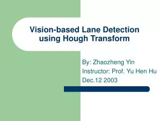
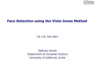
International Journal of Trend in Scientific Research and Development (IJTSRD) | ISSN: 2456-647 clusters depends on the balance of small line segments [10]. 2. Methodology 2.1 Road Image Analysis The road image captured by the camera mounted in front of the car will contain several objects, but there are two important objects for this research, the road itself and the lane marks. The lane marks most probably appear in certain region(s) of the image. The nearer the region to the car, the higher probability of the lane mark existing. Bing-Fei et al [11] define this region as Region of Interest (ROI), and a small region inside the ROI called Search Window is used to detect lane marks. The search window slides from left to right to search lane marks. Zhu et al [8] proposed Detection Window (DW) as search and used Otsu algorithm to detect lane marks. In this paper, instead of using search window we have used a line slicing the image from left to right as a region to detect lane marks. With this, the problem is reduced to a one- dimension problem. 2.2 Lane Detection Method Detection can be done by analyzing the whole image [4] or by analyzing the image region by region [6][8]. Color, shape, and texture are three features that are widely used in object detection process. Since most of the objects have different intensity compared to their background, edge feature is used to detect any object’s existence in the image. To identify the object we will need additional features that make the object specifically differ from the other objects. Color and shape are attributes that we can use for object identification. Since lane marks are a rectangular white object, as the steps to detect the object then we first need to detect the strong edge and check the color component of the pixel next to the edge. In this research, we have used one-pixel width line as a search window. If a horizontal line is passing through a road image and if the line intersecting lane marks, we can say that the line has detected the road lane. The intersection can be determined by analyzing pixels that lie along the line. Let f(m,n) represent a road image with n={1,2,………W} and I(j) is intensity values of the pixel along the horizontal line k pixel above the bottom of the image a. I(j) = f(k,j), {j : j = 1,2,……W} We can calculate the pixel gradient value by using first derivative Gauss mask. The use of first derivative Gaussian mask will result in gradient value of smoothed image [12]. dI(n) = I(n) DG(n) Edge point is pixels with high gradient ��(��) = ���(�) ?� ���(�) > �ℎ���ℎ���� dI(n){ 0 ?� ���(�) < �ℎ���ℎ�? Not all edges come from lane marks, so another step is required to complete detection process. An edge belongs to a lane mark if the number of its neighboring pixels has a lane mark characteristic. Lane marks are mostly in white color (sometimes also yellow or red), so the lane detection criteria is to check if there is a set of pixels that have all white pixel criteria. Since white color has the same value for each RGB component, the criteria for lane pixel is that all RGB color component should be above a threshold value. Based on our study, most of the lane marks have RGB component value above 200. After the gradient and color criteria were set we developed an algorithm to detect lane marks along the horizontal line. Set vertical position Repeat I(n) = gray value along horizontal direction Set first derivative Gauss mask dI(n) = I(n) DG(n) Search dI(n) > threshold If found For each pixels If all RGB component > threshold2 Record dI(n) coordinates as lane edge. Else continue searching until right end Set new vertical position Until the whole ROI is covered. 2.3 Detection Result After the algorithm was implemented in Matlab programming language, the method was tested to a good quality road image. We selected good quality because the method was a new method. We also defined the ROI of the image was of 2/3 bottom part of the image. The following figure shows the usage of one of the good quality images to test the proposed method and the first search window line. m={1,2,…….H} and @ IJTSRD | Available Online @ www.ijtsrd.com | Special Issue Publication | November 2018 P - 193
International Journal of Trend in Scientific Research and Development (IJTSRD) | ISSN: 2456-647 Figure1. Image sample and its search window. (Image source: https://www.linkedin.com/pulse/weekend- hack-lane- detection-drift-self-driving-srinath-sridhar.) The good image has clear white color lane marks with almost no dirt and occlusion. This kind of image can be easily found in most highways. The additional line at the bottom of the image is the search window that sample pixels data. From the image we can see that along the line there will be some intensity discontinuity because the line intersect lane mark as shown in the following figure. Figure3. Gradient distribution From the gradient distribution graph, we can see there were two high positive gradients. Each high gradient pixel followed by one very high negative gradient. The high positive gradient pixel appears when there was a transition from gray pixels (not-marked road) to white pixels (road lane mark). From the graph also we can set a threshold value to classify the pixel as lane edge candidate. For this experiment, we set 40 as threshold value positive gradient and -40 for the negative gradient. If we put both pairs of pixels, we can see that the points are the edges’ lane as shown in the following figure. Figure4. High positive and high negative gradient pixel To ensure that the high gradient point belongs to a lane mark, we need to make color component test to the pixels that lie between the pair of edges. To demonstrate that a lane mark was detected, the pixel belongs to the lane mark changed to green. The result for the color component test is shown in the following figure. Figure2 . Pixel intensity distribution There were three peaks appearing in the distribution graph, two come from the lane marks which have very high intensity and one peak from the shadow-like object. If we convolve the intensity data with first derivative Gaussian, we will get gradient distribution as shown in the following figure. Figure5. Lane marks detected by the line @ IJTSRD | Available Online @ www.ijtsrd.com | Special Issue Publication | November 2018 P - 194
International Journal of Trend in Scientific Research and Development (IJTSRD) | ISSN: 2456-647 The following result demonstrates how the system can avoid positive false result. The high gradient was detected but the result was no lane detected (no green line). 4.References 1.Q. Li, L. Chen, M. Li, S. Shaw and A. Nuchter, “A Sensor-Fusion Drivable-Region and Lane- Detection System for Autonomous Vehicle Navigation in Challenging Road Scenarios”, IEEE Transactions on Vehicular Technology, vol. 63, no.2, p. 540, 2014. 2.L. Mars, R. Mahsan, S. Stefano, S. Majid, “SmartLDWS: A Robust and Scalable Lane Departure Warning System for the Smartphones”, IEEE Conference on Intelligent Transportation Systems, Proceedings, 10.1109/ITSC.2009.5309685. ITSC. 1 - 6. Figure6. Positive false test result With this result, we can conclude that the method was accurate enough to detect lane marks. The process repeated for detecting lane marks in the whole image. The set of lane marks position is crucial in providing vehicle behavior to the driver. For visual presentation, the program will change the color of lane marks to green color at the pixels that intersect the marks. The overall detection result is presented in the following figure. 3.X. Liu, X. Xu, and B. Dai, “Vision-based long- distance lane perception and front vehicle location for autonomous vehicles on highway roads”, J. Cent. South. Univ., 19:1454–1465, 2012 4.C Tu, B. J. van Wyk, Y. Hamam, K. Djouani, S. Du, “Vehicle Position Monitoring Using Hough Transform”, International Electronic Engineering and Computer Science (EECS 2013). Conference on 5.S. Yenikaya., G. Yenikaya, and E Duven, “Keeping the vehicle on the road – A survey on on-road lane detection systems”, ACM Comput. Surv. 46, 1, Article 2 (October 2013), 6.S. G. Jeong, C. S. Kim, D. Y. Lee, S. K. Ha, D. H. Lee, M. H. Lee and H. Hashimoto, “Real - time lane detection for autonomous vehicle”, ISIE 2001, Pusan, KOREA Figure7. Positive false test result 7.C. Rosito, Jung and C. R. Kelber, “An Improved Linear-Parabolic Model for Lane Following and Curve Detection”, Proceedings of the XVIII Brazilian Symposium on Computer Graphics and Image Processing (SIBGRAPI’05) When the detection processes are performed for the whole image each time the line crossing lane marks, the program will automatically record the edge of the detected lane marks. 3.Conclusion In this paper, we have presented a novel method for lane marks detection. The method used 1D line as search window to detect lane marks. By using a simple threshold for gradient data and RGB color components, the method can smartly and successfully detect the lane marks. With a small number of pixels to be analyzed for each detection steps and simple mathematical calculation involved in the analysis, this method promises to fulfill one of the criteria for good lane detection method set by Narote et al [13]. For further research, we need to test the effectiveness of the method for real road image captured in different conditions. 8.S. Zhu, J. Wang, T. Yu, J. Wang, “Method of Lane Detection and Tracking for Expressway Based on RANSAC”, Conference on Image, Vision and Computing 2017. 2nd International 9.Y. He, H. Wang, B. Zhang, “Color Based Road Detection in Urban Traffic Scenes Color-based road detection in urban traffic scenes”, IEEE Trans. Intelligent Transportation Systems 5(4): 309-318 (2004) 10.J. Niu, J. Lu, M. Xu, L. Pei, X. Zhao, “Robust Lane Detection using Two-stage Feature @ IJTSRD | Available Online @ www.ijtsrd.com | Special Issue Publication | November 2018 P - 195
International Journal of Trend in Scientific Research and Development (IJTSRD) | ISSN: 2456-647 13.S. P. Narote, R. P. Bhujbal, A. S. Narotec, D. M. Dhane, “ Review of recent advances in lane detection and departure warning system”, Pattern Recognition 73 (2018) 216–234. Extraction Recognition 59 (2016)225–233 with Curve Fitting”, Pattern 11.W. Bing-Fei, L. Chuan-Tsai, C. Yen-Lin, “Dynamic Calibration and Occlusion Handling Algorithms for Lane TRANSACTIONS ELECTRONICS, VOL. 56, NO. 5, MAY 2009 14.G. Matthias, A. Matthias, B. Martin, F. Georg, H. Falk, H. Bernd, K. Sven, N. Robert, P. L. Fernando, R. Florian, R. Martin, S. Michael, T. Michael, W. Cheng, J. W. Hans, “Design and Capabilities of the Automobile”, IEEE Symposium, Eindhoven, The Netherlands, June 4- 6, 2008. Tracking”, INDUSTRIAL IEEE ON 12.R. C. Gonzalez and R. E. I. Woods, “Digital image processing” (3rd ed.). Upper Saddle River, N.J.: Prentice Hall. MLA, (2008). Munich Intelligent Cognitive Vehicles @ IJTSRD | Available Online @ www.ijtsrd.com | Special Issue Publication | November 2018 P - 196