Download

1 / 32
320 likes | 438 Views
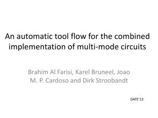
An automatic tool flow for the combined implementation of multi -mode circuits. Brahim Al Farisi, Karel Bruneel, João Cardoso, Dirk Stroobandt. Overview. Multi-mode circuit FPGA Dynamic reconfiguration: Modular d ynamic reconfiguration (MDR) Dynamic circuit specialization (DCS)

E N D
An automatic tool flow for the combinedimplementation of multi-mode circuits Brahim Al Farisi, Karel Bruneel, João Cardoso, Dirk Stroobandt
Overview • Multi-mode circuit • FPGA • Dynamic reconfiguration: • Modular dynamic reconfiguration (MDR) • Dynamic circuit specialization (DCS) • Novel tool flow • Experiments and results • Conclusions • Future work
Multi-mode circuit • Several circuits, called modes, that are used mutually exclusive in time • Example: software defined radio • Goal: Area efficient implementation through hardware resource sharing
FPGA FF LUT 0 0 1 0 0 0 1 0 0 1 1 0 0 1 0 1 1 1 1 0 0 1 1 0 0 0 0 0 0 1
Conventional FPGA tool flow HDLdesign SYNTHESIS MAP LUT circuit PLACE ROUTE Configuration Input: textual description of functionality
Textual description: HDLdesign in0 entity multiplexer is port( sel : in std_logic_vector(1 downto 0); in : in std_logic_vector(3 downto 0); out : out std_logic ); end multiplexer; architecture behavior of multiplexer is begin out <= in(conv_integer(sel)); end behavior; in1 out in2 in3 sel0 sel1
Conventional FPGA tool flow HDLdesign SYNTHESIS MAP LUT circuit 100101 011100 001111 PLACE ROUTE Configuration Input: Textual description of functionality Internal representation: LUT circuit Output: FPGA configuration
Dynamic reconfiguration of FPGAs M3 M3 M1 M1 M2 M2 • Advantages: • Smaller area • Lower power usage • Increased speed • Disadvantage: • Reconfiguration time • Goal: area reduction with reduced reconfiguration time
Dynamic reconfiguration of FPGAs M3 M3 M1 M1 M2 M2 • 2 tool flows: • Modular Dynamic Reconfiguration (MDR) • Dynamic Circuit Specialization (DCS)
Modular Dynamic Reconfiguration (MDR) Mode 1 Mode 2 SYNTHESIS SYNTHESIS MAP MAP PLACE PLACE ROUTE ROUTE Configuration 1 Configuration 2
MDR • Different modes are implemented independently • Complete area is rewritten Results in long reconfiguration times
Dynamic Circuit specialization • Design with parameters: input signals that only change once a while • Implement dependency on parameters using dynamic reconfiguration
Dynamic circuit specialization Param. HDL SYNTHESIS TMAP Tunable circuit TPLACE TROUTE Param. Conf. Input: annotatedtextual description of functionality
Parameterised HDL design entity multiplexer is port( --BEGIN PARAM sel : in std_logic_vector(1 downto 0); --END PARAM in : in std_logic_vector(3 downto 0); out : out std_logic ); end multiplexer; architecture behavior of multiplexer is begin out <= in(conv_integer(sel)); end behavior; in0 in1 out in2 in3 sel0 sel1
Dynamic circuit specialization Param. HDL SYNTHESIS TMAP Tunable circuit TPLACE TROUTE Param. Conf. Input: Annotatedtextual description of functionality Internal representation: Tunable Circuit
Tunable circuit Tunable look-up table Tunableconnection
Dynamic circuit specialization Param. HDL SYNTHESIS TMAP Tunable Circuit 1A0101 0111B0 0C1111 A= sel0AND sel1 B= sel1 C= sel0OR sel1 TPLACE TROUTE Param. Conf. Input: Annotatedtextual description of functionality Internal representation: Tunable Circuit Output: Parameterised configuration
Dynamic Circuit Specialization • Reduced reconfiguration time • Takes as input 1 parameterised design • How to implement several modes with DCS?
Goal of our research • Develop tool flow for dynamic reconfiguration of multi-mode circuits • Reduce reconfiguration time • Combined implementation of different modes: Utilize similarities Increase correlation between configurations of the different modes
Novel tool flow Mode 1 Mode 2 SYNTHESIS SYNTHESIS MAP MAP PLACE PLACE ROUTE ROUTE Merge Configuration 1 Configuration 2 TROUTE Param. Conf.
Combined placement: virtual 3D FPGA • Simultanous placement of different LUT • circuits on FPGA • Extension of a simulated annaeling placer
Different cost functions • CFRT: estimation of reconfiguration time • (= number of switches that need to be rewritten in the routing) • CFWL: estimation of total wire length Tunable circuit
Reconfiguration time optimization • Uses “edge matching” - previously proposed * • Try to overlap connections of different modes • Connections that overlap don’t require parameterised bits in the routing *M. Rullmannand R. Merker, “Maximum edge matching forreconfigurable computing,” Parallel and Distributed Processing Symposium, International, vol. 0, p. 179, 2006.
Wire-length optimization • Cost function that estimates total wire length needed by TRoute to implement Tunable circuit
Experiments • Implemented novel tool flow in our JAVA version of VPR • Regular expression matching hardware, constant coefficient FIR filters, and general MCNC benchmarks • Circuits of 200-400 LBs • Only 2 modes considered • Comparison of MDR and DCS (this work) • Metrics: • Reconfiguration time • Wire length (of each mode separately)
Conclusions • Using combined placement and DCS: • Around 5X speedup of reconfig. time • Limited increase in wire length • Better to optimize for wire length during combined • placement: this also reduces reconfiguration time!
Future work • Combining logic circuits instead of LUT circuits • Take configuration frames into consideration
An automatic tool flow for the combined implementation of multi-mode circuits Questions?