Download
1 / 20
210 likes | 387 Views
Equivalent circuit for field flatness tuning of a transverse deflecting cavity. Louise Cowie. Contents. The transverse deflecting cavity Resonant model Simplified model Testing the model using a simulation Measuring E z Preliminary data Summary. VELA. TDC.

E N D
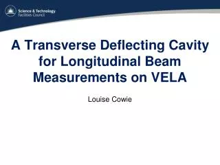
Equivalent circuit for field flatness tuning of a transverse deflecting cavity Louise Cowie
Contents • The transverse deflecting cavity • Resonant model • Simplified model • Testing the model using a simulation • Measuring Ez • Preliminary data • Summary
TDC • S-band cavity operating at 2.9985 GHz and providing a 5 MV kick • The cavity gives each electron in the bunch a transverse kick that is proportional to its position • Converts longitudinal to transverse distribution
Transverse force • The force on an electron is • To give an electron travelling in the z direction a transverse kick in the y direction requires either -An electric field in the -y direction -A magnetic field in the x direction • Use what is known as a dipole-like mode: TM1np, TE1np
TM110 Magnetic field force
Beam pipe E field Electric field
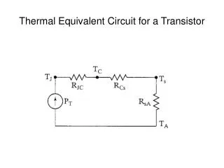
Resonantly coupled circuit • The cavity can be modelled as a resonantly coupled LC circuit • The coupling factor k becomes • k has a frequency dependence
The problem • For the perturbation theory method we need an eigenmatrix whose eigenvalues are defined as • We cannot use a frequency dependent k inside this matrix.
Simplified model • The resonance of the mode in the iris is higher than the cavity frequency. The inductor dominates so the coupling can be represented as an inductor • The inductor strength varies symmetrically along the cavity, so k varies in the same way Cb Cb
Coupling constants • The cavity is optimised to have the same H field in each cell, but the E field in each cell is not the same • We use an iterative optimisation process to find the k values which match this field profile
Coupling constants • The expected normalised current in each cell is found from the matrix using approximate k values using Kirchoff’s loop rule. • This is compared to the expected normalised E field values in each cell, as calculated in CST MWS • An iterative simplex optimisation process is used to find the optimal k values to minimise the difference
Optimised model • The final k values are then used in the matrix and the eigenvalues are calculated to find the resonant frequencies of the modes in the dipole pass-band. • The model is good at the Pi mode but diverges at higher modes. • A frequency error will have contributions from all the modes, so testing is required to see if this poses a problem Freq (GHz) π mode Modes
Testing the model • Modelled the cavity in CST with a deformed 3rd cell • Extracted the E field in the z direction at cell centres • Used model and perturbation theory to find the cell with the error
Result of test Frequency error (Hz) Cell
Measuring Ez • There are transverse (x-y) and longitudinal (z) components of the E and B fields • The only field component in the cell which has no contribution from the coupling iris is Ez. This corresponds to the capacitor C in the resonantly coupled circuit
Measuring Ez • On axis the only E field is transverse • To measure only the longitudinal E field in the we must measure the E field off axis, at those points along the axis where the transverse field is zero (eg. where E on axis is zero)
Real measurements Measured Simulated
Summary • The transverse deflecting cavity is a dipole mode cavity • A simplified circuit model was defined • The model was optimised for the particular cavity and tested through simulation to detect frequency errors • A method of measurement of Ezwas described
Acknowledgements Thanks to Philippe Goudket, Graeme Burt, Alan Wheelhouse and Steve Buckley.