Download
1 / 31
310 likes | 1.02k Views
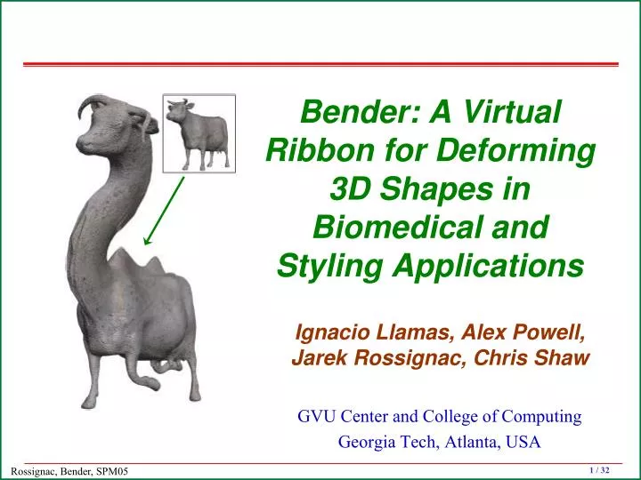
Bender: A Virtual Ribbon for Deforming 3D Shapes in Biomedical and Styling Applications Ignacio Llamas, Alex Powell, Jarek Rossignac, Chris Shaw GVU Center and College of Computing Georgia Tech, Atlanta, USA Digital Clay: A leap in human/shape interaction

E N D
Bender: A Virtual Ribbon for Deforming 3D Shapes in Biomedical and Styling Applications Ignacio Llamas, Alex Powell, Jarek Rossignac, Chris Shaw GVU Center and College of Computing Georgia Tech, Atlanta, USA
Digital Clay: A leap in human/shape interaction NSF-ITR/PE+SY project 0121663 at Georgia Tech. Allen, Book, Glezer, Ebert-Uphoff, Rosen, Rossignac, Shaw
EL f(d) P SL 1 OL d 0 1 Space warp based on a screw motion “Twister: A space-warp operator for the two-handed editing of 3D shapes”, Llamas, Kim, Gargus, Rossignac, and Shaw. Proc. ACM SIGGRAPH,July 2003. Decay function
Q E S K The universal screw-motion • Screw motions are great! • Uniquely defined by start pose S and end pose E • Independent of coordinate system • Subsumes pure rotations and translations • Minimizes rotation angle & translation distance • Natural motions for many application • Simple to apply for any value of t in [0,1] • Rotation by angle tb around axis Axis(Q,K) • Translation by distance td along Axis(Q,K) • Each point moves along a helix • Simple to compute from poses S and E • Axis: point Q and direction K • Angle b • Distance d Screw Motion
Screw history (Ceccarelli [2000] Detailed study of screw motion history) • Archimede (287–212 BC) designed helicoidal screw for water pumps • Leonardo da Vinci (1452–1519) description of helicoidal motion • Dal Monte (1545–1607) and Galileo (1564–1642) mechanical studies on helicoidal geometry • Giulio Mozzi (1763) screw axis as the “spontaneous axis of rotation” • L.B. Francoeur (1807) theorem of helicoidal motion • Gaetano Giorgini (1830) analytical demonstration of the existence of the “axis of motion” (locus of minimum displacement points) • Ball (1900) “Theory of screws” • Rodrigues (1940) helicoidal motion as general motion • …. • Zefrant and Kumar (CAD 1998) Interpolating motions
Volume swept during screw motion Computing and visualizing pose-interpolating 3D motions Jarek Rossignac and Jay J. Kim, CAD, 33(4)279:291, April 2001. SweepTrimmer: Boundaries of regions swept by sculptured solids during a pose-interpolating screw motion Jarek Rossignac and Jay J. Kim
Smoothing piecewise-screw motions “ScrewBender: Polyscrew Subdivision for Smoothing Interpolating Motions” A. Powell and J. Rossignac
Collision during screw motions "Collision Prediction for Polyhedra under Screw Motions", BM Kim and J. Rossignac, ACM Symposium on Solid Modeling and Applications, 2003. • Helix isV(t) = rcos(tb)i+rsin(tb)j+tdkin screw coordinates • The screw intersects plane d+V(t)•n= 0 for values of t satisfying
P’ EL U’ O’ V’ d (O+O’)/2 P axis K b SL V Q U O I Computing the screw parameters From initial and final poses: M(0) and M(1) K:=(U’–U)(V’–V); K:=K / ||K||; b := 2 sin–1(||U’–U|| / (2 ||KU||) ); d:=K•OO’; Q:=(O+O’)/2 + (KOO’) / (2tan(b/2)); To apply a t-fraction of the screw: Translate by –Q; Rotate around K by tb; Translate by (0,0,td); Translate by Q;
f(d) L(0.5) EL 1 L(1) SL OL d 0 1 Single-hand warp and decay • SL and EL are interpolated by a screw motion L(t), t in [0,1] • A point p moves by L(f(||POL||/r)), f(d)=cos2(d/2) if d<1 and 0 otherwise • The grabbed point is subject to the whole motion L(1) • Points outside of the region of influence (RoI) don’t move • The warp is smooth 3D radial decay profile
R L Two-hand warp • Want to use two hands simultaneously to deform a shape • A point P moves to P + (L(fL(P)) – P) + (R(fR(P)) –P) • Squash overlapping RoI
Some models designed in TWISTER • Implemented in C++, using OpenGL • Realtime feedback (~20 fps with 30,000 vertices) • Pentium III 866 Mhz, 256 MB RAM, NVIDIA Quadro 900 XGL • Adaptive subdivision
From design to animation • Design one feature at a time • Then animate their synchronized creation
Limitations of TWISTER Bends and extrusions are tedious with Twister
BENDER’s Approach • Artificial ribbon • User controls its shape (wire) and twist with both hands • Tube surrouding the ribbon is deformed (decay function)
Controlling the ribbon with two hands Each tracker controls one end of the ribbon The central wire of the ribbon is a G1 bi-arc curve I0=P0+aT0 I1=P1–bT1 ||I0–I1||=a+b J=(bI0+aI1)/(a+b) Solve with a=b “Piecewise-Circular Curves for Geometric Modeling", J. Rossignac and A. Requicha. IBM Journal of Research and Development, Vol. 13, pp. 296-313, 1987.
Twisting the ribbon • Compute total twist • Use angle between P0I0J plane and tracker orientation at P0 • Propgate it (pure rotation) to J • Compute total twist at J between the two arcs • Distribute total twist evenly along the wire
Parameterized pose along the ribbon • Parameterise the wire: s in [0,1] • Move the origin along the wire by an arc-length fraction s • Get a Frenet trihedron (need only a rotation) • Perform an fraction of the total twist around the tangent
Interpolating two ribbons • When a button is pressed, the grabbed ribbon is captured • We compute a deformation that maps it into the current ribbon (during editing) or the final ribbon (upon release) • The deformation maps each pose Gs of the grabbed ribbon into the corresponding pose Ps of the current ribbon • The mapping is a screw motion! Gs Grabbed ribbon s Screw (Gs,Ps) Current ribbon
Preventing flips • The screw axis, K, may flip between consecutive values of s • If so, we reverse it (which may lead to rotations >180o)
Warping space with a decay • To warp a point Q, we compute the parameter s of its closest projection(s) on the grab wire • Then, we apply a fraction f of Screw(Gs,Ps) • f depends on the distance from Q to the closest projection • Decay function • Plateau option
Avoiding tear (two-hand twister) • Q may have one closest projection on each arc of the wire • We use the two-hand version of Twister to blend the corresponding screw motions
Adaptive subdivision • The triangulation is automatically refined where needed
Sculpting walls • Make and edit complex features with only a few gestures
Twisting ears • Position ribbon along the ear axis • Grab and bend or twist • Release
Supporting surgery planning • 0.2% of babies in the US are born with a single ventricle. • Surgeons want a tool to design the shape of the Fontan repair (cavopulmonary connection placing thepulmonary and systemic circuits in series with the univentricular heart).
Conclusions and future work • Twister: effective and intuitive human/shape interaction, • Bender: adds support for elongated features • What is missing: • Force feedback to align the cursors with a surface • Aligning the ribbon with a surface (automatic snap) • Automatic alignment of wire with centerline of tubes