Download
1 / 16
160 likes | 280 Views
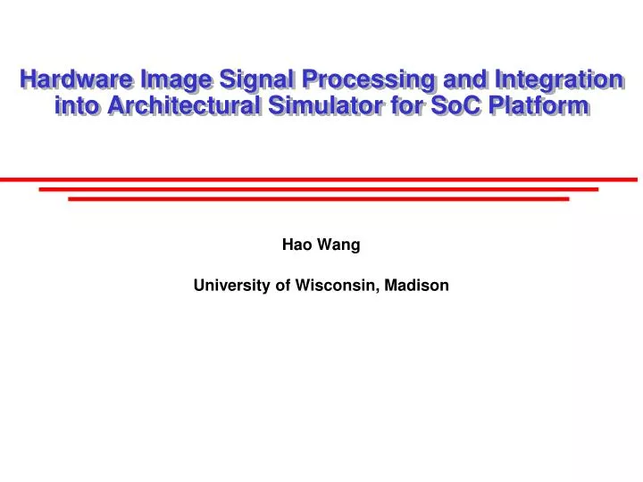
Hardware Image Signal Processing and Integration into Architectural Simulator for SoC Platform. Hao Wang University of Wisconsin, Madison. Outline. Introduction on SoC Motivation Verilog implementation of JPEG encoder Integrated SoC simulator Future work. System-on-Chip Platform.

E N D
Hardware Image Signal Processing and Integration into Architectural Simulator for SoC Platform Hao Wang University of Wisconsin, Madison
Outline • Introduction on SoC • Motivation • Verilog implementation of JPEG encoder • Integrated SoC simulator • Future work
System-on-Chip Platform • Mobile computing – New driving force • Smartphones, Tablets • SoC – Popular solution • Qualcomm’s Snapdragon, Samsung’s Exyons • General-purpose CPU, Graphics processing, Application-specific accelerators, Modem, etc.
Resource Management on SoC • Schematic of Snapdragon SoC
Resource Management on SoC • Memory bandwidth is the most critical resource shared on SoC Shared Memory Channel
Motivation • Heterogeneous system • CPU – Sensitive to memory latency • GPU – High bandwidth demand, real-time deadline • DSP, multimedia processor – Low response latency requirement • Key problem • No architectural simulator available for SoC platform • Integrated CPU-GPU simulator: http://cpu-gpu-sim.ece.wisc.edu/ • Goal of this project • Design a hardware JPEG encoder using Verilog • Write an architectural model for the hardware encoder • Integrate into a CPU simulator (gem5) as one step to build an architectural simulator for SoC platform
JPEGEncoder (Verilog) Implementation • Matlab generates input matrix; read by testbench; • Input 8x8 blocks of data (24-bit) into the encoder; one pixel per clock cycle; • Operand collector to ensure the full block is ready • To tolerant variable memory access latency • RGB to YCbCr conversion • DCT on 8x8 blocks • Quantization; multiply (2^13/Qij) then right shift • DPCM and Huffman Encoding for DC components; • RLE and Huffman Encoding for AC components; • Bit streams coming from Y, Cb and Cr are combined to form an output stream (temporal multiplexing)
JPEG Encoder Result tif format 768KB output jpg format 68KB
Synthesis Result & Throughput • Synopsys Design Compiler • TSMC 45nm general-purpose library, 800MHz • ~1.0e7 blocks per sec
Simulator Integration • Difficult to find a standard • Which hardware components to include? • Low level implementation details: pipelining, circuit design, etc. • Use Trimaran instead • A widely-used compilation/architecture infrastructure • General VLIW/Application-specific processor • Configured to model DSP processor • JPEG encoder on Trimaran • Software implementation • 9.16e7 cycles @ 1GHz – 91.6ms ( verilog design ~0.4ms )
Simulator Integration • Still separate process; communicate using shared memory structure in Linux OS; • Memory Requests on Trimaran side will be feed to CPU simulator (gem5) side; simulate the DRAM timing and respond; gem5 (CPU) Trimaran (DSP) Shared memory tick set clock tick Tick scheduler reset Response queue Request queue L2 cache Request queue Memory subsystem (M5) Memory subsystem (M5)
Future Work • Figure out how Trimaran simulates timing info • Get lock-step execution done • Figure out real-world usage scenario • Real research – writing papers – graduate
Some Details • RGB – YCbCr • 24-bit in; 24-bit out; • Pipelined; 3 cycles; 1 – mult; 2 – sum; 3 – rounding; • DCT • 8-bit in, pipelined; 64 11-bit output; • Internal 32-bit; • Output_enable set when input enable unset, so requiring idle cycle between 8x8 blocks • Quantization • 4 cycles; 1 – latch in; 2 – quantify; 3 – buffer; 4 – rounding; • Huffman Encoding • DC calculated first, AC calculated in zigzag order; • Totally 13 cycles inserted between 8x8 blocks
Some Details • FIFO buffer • Check for 0xFF in the bitstream, add a dummy 0x00; • Append 0xFFD9 at the end • Post-processing • MATLAB generates JPEG header and standard Huffman table • Then get the actual JPEG file