Download
1 / 12
130 likes | 309 Views
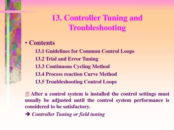
13. Controller Tuning and Troubleshooting. Contents 13.1 Guidelines for Common Control Loops 13.2 Trial and Error Tuning 13.3 Continuous Cycling Method 13.4 Process reaction Curve Method 13.5 Troubleshooting Control Loops.

E N D
13. Controller Tuning and Troubleshooting • Contents 13.1 Guidelines for Common Control Loops 13.2 Trial and Error Tuning 13.3 Continuous Cycling Method 13.4 Process reaction Curve Method 13.5 Troubleshooting Control Loops • After a control system is installed the control settings must usually be adjusted until the control system performance is considered to be satisfactory. • Controller Tuning or field tuning
Flow control ; Fast response, no time delay Use PI controller with intermediate No D-mode because of high frequency noise 13.1 Guidelines for Common Control Loops - Controller tuning is usually done by trial and error, it can be quite tedious and time consuming Guidelines are needed. • The following guidelines can be used with user’s discretion and useful where a process model is not available. • Liquid level ; Integrating process Use P or PI controller with high gain D-mode is not suitable since level signal is usually noisy due to the splashing and turbulence of the liquid entering the tank
Gas pressure ; Fast response Use PI controller with large • Temperature ; Various characteristics with time delay. Use PID or PI controller (D-mode can accelerate the response) • Composition ; Noisy, large time delay Recommend to use advanced control technique
A typical trial and error approach for PID controllers 1) Eliminate integral and derivative action by setting at its minimum value and at its maximum value. 2) Set at a low value and put the controller on automatic. 3) Increase until sustained oscillation occurs. 4) Reduce by a factor of two. 5) Decrease until sustained oscillation occurs. 6) Set as . 7) Increase until sustained oscillation occurs. 8) Set as . 13.2 Trial and Error Tuning • Note ; In performing the experimental test, it is important that the controller output dose not saturate. If saturation dose occur, then a sustained oscillation can result even though .
Figure 13.1. Experimental determination of the ultimate gain . • Ultimate gain ; The ultimate gain is the largest value of the controller gain that results in closed-loop stability when a proportional-only controller is used.
1) Quite time-consuming for trials. very expensive. 2) External disturbance or change in the process during controller tuning. unstable operation or hazard situation. 3) Not applicable to processes that are open-loop unstable because such processes typically are both high and low value of . 4) Not applicable to processes that do not have an ultimate gain. some simple processes do not have an ultimate gain( e.g., processes that can be accurately modeled by first-order or second order transfer functions with time delays • Disadvantages of the trial and error tuning approach
13.3 Continuous Cycling method • Ultimate period ; the period of the resulting sustained oscillation. • Procedure Step 1. Determine experimentally and . Step 2. Calculate the PID controller settings using Ziegler- Nichols tuning relations inn Table 13.1. • Ziegler and Nichols in 1942. • This method has also been referred to as loop tuning or ultimate gain method. • Empirically developed to provide a decay ratio.
For less oscillation, there are the modified Z-N settings in Table 13.2. • Continuous cycling method has some of same disadvantages as the trial and error method. However, the continuous cycling method is less time-consuming than trial and error method because it requires only one trial and error search.
13.4 Autotuning • Astrom and Hagglund “Automatic Tuning of PID controllers”. AIChE Journal, 28, 434, 1982 • An alternative to Ziegler-Nichols continuous cycling method. • Ultimate gain and period can be obtained without trial and error procedure. Figure 13.2. Autotuning using a relay controller.
where is the relay amplitude set by the operator, and is the measured amplitude of the process oscillation. • Advantages 1. There is a single user-specified parameter: . 2. It dose not require a priori information about process except the sign of the static gain. 3. The process operating condition can remain within a bound which can be adjusted not to disturb the process too much. • Procedure of Autotuning 1. The system is forced by a relay controller which causes the system to oscillate with a small amplitude. 2. Ultimate gain and period are obtained. 3. The controller settings are then found using Z-N rule(table 13.1)
Definition ; slope of the tangent line through the inflection point. where is the magnitude of the step change that was introduced in controller output . ; time at which the tangent line intersects time axis. 13.5 Process Reaction Curve Method • Ziegler and Nichols in 1942.
Advantages 1. Only a single experimental test is necessary. 2. It dose not require trial and error procedure. 3. The controller settings are easily calculated. • Disadvantages 1. The experimental test is performed under open-loop conditions. Disturbance should be eliminated during the test. 2. Inflection point is not easy to find if the measurement is noisy and a small record chart is used. 3. The method tends to be sensitive to controller calibration errors in . the Z-N method is less sensitive to calibration error in , since the controller gain is adjusted during the experimental test. 4. The recommend settings in the Table 13.3 tend to result in oscillatory response. 5. The method is not recommended for processes that have oscillatory response.