Download
1 / 25
260 likes | 560 Views
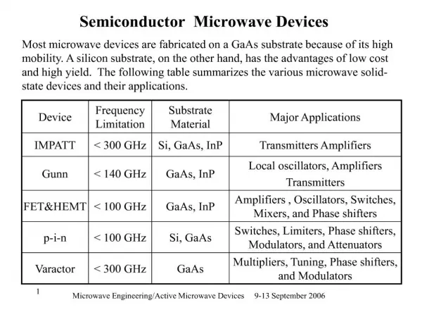
Input & Output Devices Display Devices. Kocaeli University Computer Engineering Advanced Computer Graphics Spring 2012. Input Devices. Alphanumeric Input Keyboards 2D Inputs (Joystick, Mouse, etc) 3D Inputs Glove, Space, ball Image Inputs Camera, Scanner. Output Graphic Devices.

E N D
Input & Output DevicesDisplay Devices Kocaeli University Computer Engineering Advanced Computer Graphics Spring 2012
Input Devices • Alphanumeric Input • Keyboards • 2D Inputs • (Joystick, Mouse, etc) • 3D Inputs • Glove, Space, ball • Image Inputs • Camera, Scanner
Output Graphic Devices • Color Raster CRT • Calligraphic (vector) CRT • Flat-panel displays: • Color LCD (Liquid Crystal) • Plasma Display • Hardcopy Devices • Printers
CRT • Cathode Ray Tube • Enclosed vacuum tube; electron beam is focused toward front surface of the tube, which is coated in phosphor • Single gun for monochrome and three guns for color • High voltage reduces the electron density and thus brightness Vertical and horizantal reflection plates
CRT -Cont • Technology relatively old; has disadvantages • Physical size and weight • Power consumption • Random scan display (Vector Display) & Rater scan display
Vector Displays • Random scan display • Also called • vector, • stroke-writing, • or calligraphic displays. • The electron beam directly draws the picture in any specified order. • A pen plotter is an example of such a system
Raster Displays • The image is stored in a frame buffer containing the total screen area and where each memory location corresponds to a pixel. • In a monochrome system, each bit is 1 or 0 for the corresponding pixel to be on or off (bitmap). • Image is represented as a bitmap (1 bit/pixel) or as a pixmap (8 or 24 bits/pixel)
A raster-scan system displays an object as a set of points across each screen scan line (a) (b) (c) (d)
Buffers in Raster Display • Image description is stored in a memory area called refresh buffer or frame buffer • The video controller sweeps the beam across the screen, one row at a time, from top to bottom and back to the top again. • Three beams are controlled (red, green, blue) and the intensity of each color is stored in the frame buffer • To give an idea: refreshing is carried out at the rate of 60 to 80 frames/second
N-bit plane Frame buffer • Choice of the number of gray scales and colors depend on the value of N (bit plane size) • N = 1 • two colors (B&W) • N = 3 • 8 gray scales or colors • N = 8 • 256 gray scales or colors • N = 24 • 16 million colours
A single bit-plane frame Buffer • For colored displays (raster-scan), three separate color guns must be used. • Each bit plane drives a color gun
N-bit plane gray level Frame buffer • In case of one-bit for each color frame buffer, we get 8 colors
LCD • Contains matrix of liquid crystals sandwiched between two polarizing filter panels • Active and passive matrix displays • Manufactured with thin film transistor (TFT) technology • Compared with CRTs • Less contrast • Reduced size, weight, and power consumption • Higher cost • energy-efficient, have sharp picture • Contrast: how big the difference between "white" and "black"
Plasma Display • Combine elements of CRT and LCD technology • Flat panel, active matrix devices • Actively generate colored light near surface of the display; good brightness and viewing • Require more power than LCDs, less than CRTs • Shortcomings • Limited operational lifetime • Larger pixel size reduces comparative image quality when viewed from short distances
How Plasma Display Works • Plasma displays have no backlight and no color filters; each pixel contains a gas that emits ultraviolet light when electricity is applied.
Plasma • Plasma technology consists of hundreds of thousands of individual pixel cells, which allow electric pulses to excite rare natural gases-usually xenon and neon-causing them to glow and produce light. • This light illuminates the proper balance of red, green, or blue phosphors contained in each cell to display the proper color sequence from the light. • Each pixel cell is essentially an individual microscopic florescent light bulb, receiving instruction from software contained on the rear electrostatic silicon board. Look very closely at a plasma TV and you can actually see the individual pixel cell coloration of red, green, and blue bars. You can also see the black ribs which separate each.
LED TV • LED (light emitting diode) • LED TVs are a new form of LCD Television. The panel on an LED TV is still an LCD TV panel and operates with the same twisting crystals matrix. • The backlight is the difference - changing from fluorescent to LED based backlighting • Have better contrast and more accurate colors than LCD
Digital Images from Scanners and Cameras • The color and brightness of each tiny area seen by a sensor is "sampled", meaning the color value of each area is measured and recorded as a numeric value which represents the color there • Each one of these sampled numeric color data values is called a pixel • A 6 inch photograph scanned at 100 dpi will produce 600 pixels across that dimension of the image. • The scanner scanning resolution (pixels per inch) and the size of the area being scanned (inches) determine the image size (pixels) created from the inches scanned. • If we scan 8x10 inch paper at 300 dpi, we will create (8 inches x 300 ppi) x (10 inches x 300 ppi) = 2400x3000 pixels