Download
1 / 22
220 likes | 404 Views
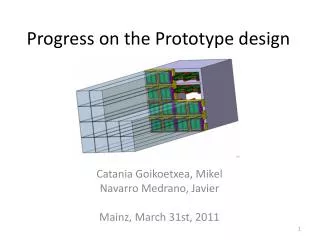
Progress on the RAL Linac Design. HIPPI Yearly Meeting – - CERN, Geneva - 29.10.2008. C. Plostinar -. Presentation outline. Upgrades for ISIS FETS Overview End to end beam dynamics simulations in FETS The new RAL linac Conclusions. TS-1. TS-2. Collimating Achromat.

E N D
Progress on the RAL Linac Design HIPPI Yearly Meeting – - CERN, Geneva - 29.10.2008 • C. Plostinar -
Presentation outline • Upgrades for ISIS • FETS Overview • End to end beam dynamics simulations in FETS • The new RAL linac • Conclusions
TS-1 TS-2 Collimating Achromat 400 MeV Linac 3 GeV 50 Hz Ring (Linac upgrade to 800 MeV) TS-3 An upgrade option for ISIS • Proposed upgrade (staged approach): • - Isis Now: 800 MeV, Beam Power: 0.16–0.24 MW • Adding a ~3 GeV RCS -> ~1MW • Adding a 400 MeV linac will increase the beam power up to 2 MW • Increasing the linac energy to 800 MeV provides upgrade options to 5 MW
Linac Layout 180 MeV Linac Layout (old) 90 MeV 3 MeV 180 MeV SCL (Side Coupled Linac) DTL (Drift Tube Linac) Front End 324 MHz 972 MHz 800 MeV Linac Layout (new) 324 MHz 648 MHz Front End DTL CCL ScL 2 ScL 1 3 MeV 193 MeV 409 MeV 75 MeV 800 MeV
Front End Overview The Front End Test Stand (FETS) H- Ion source RFQ MEBT LEBT MEBT and chopper Magnetic LEBT RFQ Laser profile monitor H− ion source
Front End Overview - The beamline support stands and rail system are installed in preparation for ion source and LEBT installation. - View of the HV cage showing the platform and installed equipment - Ion Source vessel in situ
FETS End to End Beam Dynamics Simulations RFQ MEBT LEBT Ion Source Measured (Ex=0.58, Ey=0.52) Waterbag (Ex=Ey=0.25 Pi.mm.mrad (RMS)) The measured emittance (already improved by a factor of two in the last year) is more than a factor of two larger than the waterbag particle distribution used for the optimization of the individual elements.
FETS End to End Beam Dynamics Simulations RFQ MEBT LEBT Ion Source Measured Ex=0.69, Ey=0.64 Waterbag Ex=Ey=0.33 The slight s-shaped aberrations show the influence of non linear magnetic fields on the beam transport but the emittance growth is reasonable.
FETS End to End Beam Dynamics Simulations RFQ MEBT LEBT Ion Source Waterbag Ex=0.28, Ey=0.27 Measured Ex=0.46, Ey=0.47 The large input emittance for the real beam causes large (transversal) particle loss in the RFQ which causes an overall reduction of the emittance.
FETS End to End Beam Dynamics Simulations RFQ MEBT LEBT Ion Source Waterbag Ex=0.30, Ey=0.34 Measured Ex=0.40, Ey=0.49 Particle losses in the MEBT can be neglected for the ideal case and is < 10% for the real beam distribution.
FETS End to End Beam Dynamics Simulations • Transmission more than 90% for the waterbag distribution (100% - LEBT, 95% - RFQ, 98% - MEBT) • Much higher losses when using the measured distribution – 46% transmission (100% - LEBT, 52% - RFQ, 89% - MEBT)
FETS End to End Beam Dynamics Simulations • Moderate emittance growth when using the ideal distribution • Emittance reduction when using the real distribution due to high beam loss • Efforts to reduce the ion source emittance and increase the RFQ acceptance are under way.
The H- Linac Design Key Linac Parameters: • Ion Species: H- • Energy: 3 – 800 MeV • Beam pulse current before MEBT chopping: 43mA • Beam pulse current after MEBT chopping: 30 mA • Beam power 0.5 MW • Repetition Rate: 50 Hz • Sections: • RFQ • Drift Tube Linac (4 tanks) • Coupled-Cavity Linac (56, 10 cell cavities) • Superconducting Linac (69, 5/6 cell cavities) 324 MHz 648 MHz Ion Source LEBT RFQ MEBT DTL CCL ScL 2 ScL 1 3 MeV 193 MeV 409 MeV 75 MeV 800 MeV ~11 m ~280 m
The H- Linac Design • Toshiba Klystrons (2.5 MW) • Compact PMQs (or hybrid quadrupoles?) • No of tanks: 4 (1 Klystron /Tank) • E field 2.5 MV/m • Maximum E field level: 1.5 Kilpatrick • The DTL Section • Input energy: 3 MeV • Output energy: 75 MeV • Operating frequency: 324 MHz
Klystron requirements Also needed: amplifiers for four 324 MHz MEBT bunchers, and one 648 MHz buncher between DTL4 and CCL
Studies now required: • MEBT optics re-evaluation. 2. Alternatives to DTL & CCL + Shunt Impedance Studies. 3. CCL & ScL648 & 972 MHz comparisons. 4. Refine designs of various linac stages (matching, etc.). • Error effect evaluation for the full linac. • Effect of failed superconducting cavities. 7. Design of phase ramping, ring beam line.
Conclusions • A new ISIS upgrade plan has been identified and it includes a possible 800 MeV linac • Work on the new linac has started • Work on the FETS project is progressing well