Download

1 / 17
171 likes | 325 Views
CURRENT RAMPING. Basics of Magnetism. The atomic force that can attract or repel through space, air, solid matter. An invisible field (Flux) exists between the poles of a magnet This field can be used to act upon ferrous (iron) materials

E N D
Basics of Magnetism • The atomic force that can attract or repel through space, air, solid matter. • An invisible field (Flux) exists between the poles of a magnet • This field can be used to act upon ferrous (iron) materials • Even without direct contact, magnets can influence ferrous objects
Basics of Magnetism • Each magnet has a north & south pole • Like poles repel • Unlike poles attract
Magnetic Flux • Invisible magnetic field is called Flux
Electromagnetism • Interaction between electricity & magnetism • When electricity flows through a wire, a magnetic field is setup around the wire • This field is weak, but can be detected by certain test equipment
Electromagnet • Wrapping a nail with copper wire, passing current through the wire, magnetizes the nail • The more wire & more current, the stronger the magnet field
Electromagnetic Induction • A wire carrying electricity produces an electrical current in an other wire. • The flux around the current carrying wire induces a tiny electrical current in the second wire • Passing a wire through a magnetic field will induce a voltage in the wire. • The flux will act upon the free electrons in the wire to produce electricity Ignition Coil
How a Current Probe Works • The strength of the magnetic field around a wire depends on the rate of current flow • This magnetic field induces a voltage within the probe tip. • The voltage is converted to DC and amplified. • The stronger the magnetic field the higher the voltage output from the probe.
Why use a Current Probe? • With a DMM, the circuit must be opened & the meter inserted into the circuit • With a current probe the circuit does NOT have to be disturbed! • DMM’s only give a numeric value • Current probes when used with a scope, give a graphic presentation of what is going on in a circuit
High Current Probe • Measures circuits of 0 – 600 A • For every millivolt displayed on meter, is equal to One Amp ( .250v = 250A) • Used for measuring large currents such as starter draw
Low Current Probe • Measures circuits of 0 – 60 A • Two settings: • 1mV/10mA (100mV = 1A) – used for low current testing (max 10A) • 10mV/100mA ( 10mV = 1A) – Used for high current testing (max 60A)
Here’s How it Works • Scopes measure voltage not current • Current probes measure current & convert to voltage signals • Simply clamp probe around circuit being tested • Either wire will work, remember current is the same through out the circuit
The Basics • Turn on probes, making sure battery is good • Connect probe to scope, select scale to be used, zero probe before it is clamped to wire • Clamp probe around around wire w/ arrow in direction of current flow • 10 mV Scale – for every 10 millivolts displayed on screen equals 1 amp • 100 mV Scale – for every 100 millivolts on screen equals 1 amp
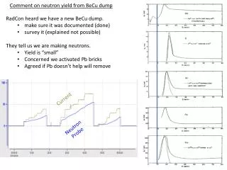
Current Ramping • Gives a true picture of what is going on with in a circuit. • In this circuit we see a gradual ramping of current as the injector is turned on. • It indicates peak current & the shift to current limiting during the hold period
Ramp Time • Is the time in milliseconds to reach peak current flow • In this illustration the current limiting section shows that the IC module can regulate max current to a safe & effective level. • This test measures the coil dynamically & can help isolate a defective IC module • We can also determine high resistance, low voltage & ground issues
Simple Measuresmensts • Current ramping a fuel pump circuit is the easiest and most effective way to look at the condition of a fuel pump • Clamp probe where ever convenient