Download
1 / 36
390 likes | 514 Views
IMT-2000. IMT-2000 stands for IMT: International Mobile Communications 2000: the frequency range of 2000 MHz and the year 2000

E N D
IMT-2000 • IMT-2000 stands for IMT: International Mobile Communications 2000: the frequency range of 2000 MHz and the year 2000 • In total, 17 proposals for different IMT-2000 standards were submitted by regional SDOs to ITU in 1998. 11 proposals for terrestrial systems and 6 for mobile satellite systems (MSSs). • All 3G standards have been developed by regional standard developing organizations (SDOs). • Evaluation of the proposals was completed in 1998, and negotiations to build a consensus among different views were completed in mid 1999. All 17 proposals have been accepted by ITU as IMT-2000 standards. The specification for the Radio Transmission Technology (RTT) was released at the end of 1999.
IMT-2000 • The (IMT-2000), consists of 3 operating modes based on Code Division Multiple Access (CDMA) technology. • 3G CDMA modes are most commonly known as: • CDMA2000, • WCDMA (called UMTS) and • TD-SCDMA (Time Division-Synchronous Code Division Multiple Access)
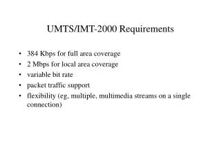
High-Speed Packet Data Services • 2 Mbps in fixed or in-building environments (very short distances, in the order of metres) • 384 kbps in pedestrian or urban environments • 144 kbps in wide area mobile environments • Variable data rates in large geographic area systems (satellite)
Network Elements from UMTS UMTS differs from GSM Phase 2+ (GSM +GPRS) mostly in the new principles for the air interface transmission WCDMA instead of TDMA/FDMA Therefore a new RAN (Radio Access Network) called: UTRAN (UMTS Terrestrial Radio Access Network) must be introduced with UMTS Only minor modifications are needed in the CN (Core Network) to accommodate the change
UTRA: UMTS Terrestrial Radio Access The most significant change in REL. ´99 was the “UTRAN”, a W-CDMA radio interface for land-based communications. UTRAN supports time (TDD) and frequency division duplex (FDD). The TDD mode is optimized for public micro and pico cells and unlicensed cordless applications. The FDD mode is optimized for wide-area coverage, i.e. public macro and micro cells. Both modes offer flexible and dynamic data rates up to 2 Mbps.
UMTS architecture • UTRAN (UTRA NETWORK) • Radio Network Subsystem (RNS) UE (User Equipment) CN (Core Network) Uu Iu UE UTRAN CN
UTRAN • Two new network elements are introduced in UTRAN • RNC • Node B UTRAN is subdivided into individual radio network systems (RNSs), where each RNS is controlled by an RNC. The RNC is connected to a set of Node B elements, each of which can serve one or several cells.
UTRAN architecture RNS RNC: Radio Network Controller RNS: Radio Network Subsystem UE1 Iub Node B Iu RNC CN UE2 Node B Node B UTRAN comprisesseveral RNSs Node B cansupport FDD or TDD orboth RNC isresponsibleforhandoverdecisionsrequiringsignalingtothe UE Celloffers FDD or TDD UE3 Iur Node B Iub Node B RNC Node B Node B RNS
UTRAN functions • Admission control • Congestion control • Radio channel encryption • Handover • Radio network configuration • Channel quality measurements • Radio resource control • Data transmission over the radio interface • Outer loop power control (FDD and TDD) • Channel coding
VLR BSS Abis BTS Iu BSC MSC GMSC PSTN Node B BTS IuCS AuC EIR HLR GR Node B Iub Node B RNC SGSN GGSN Gi Gn Node B Node B IuPS CN RNS Core network The Core Network (CN) and the Interface Iu, are separated into two logical domains: • Circuit Switched Domain (CSD) • Circuit switched service incl. signaling • Resource reservation at connection setup • GSM components (MSC, GMSC, VLR) • IuCS • Packet Switched Domain (PSD) • GPRS components (SGSN, GGSN) • IuPS
Access method CDMA • CDMA (Code Division Multiple Access) • all terminals send on the same frequency probably at the same time and can use the whole bandwidth of the transmission channel • each sender has a unique random number, the sender XORs the signal with this pseudo random number • the receiver can “tune” into this signal if it knows the pseudo random number, tuning is done via a correlation function
data1 data2 data3 data4 data5 spr. code1 spr. code2 spr. code3 spr. code1 spr. code4 scrambling code1 scrambling code2 sender1 sender2 Spreading and scrambling of user data • Constant chip rate of 3.84 Mchip/s • Different user data rates supported via different spreading factors • higher data rate: less chips per bit and vice versa • User separation via unique, quasi orthogonal scrambling codes • users are not separated via orthogonal spreading codes • much simpler management of codes: each mobile can use the same orthogonal spreading codes
Length Length SPREADING FACTOR
CDMA in theory • Sender A • sends Ad = 1, key Ak = 010011 (assign: „0“= -1, „1“= +1) • sending signal As = Ad * Ak = (-1, +1, -1, -1, +1, +1) • Sender B • sends Bd = 0, key Bk = 110101 (assign: „0“= -1, „1“= +1) • sending signal Bs = Bd * Bk = (-1, -1, +1, -1, +1, -1) • Both signals superimpose in space • interference neglected (noise etc.) • As + Bs = (-2, 0, 0, -2, +2, 0) • Receiver wants to receive signal from sender A • apply key Ak bitwise (inner product) Ae = (-2, 0, 0, -2, +2, 0) Ak (-2, 0, 0, -2, +2, 0) (-1, +1, -1, -1, +1, +1)= 2 + 0 + 0 + 2 + 2 + 0 = 6 • result greater than 0, therefore, original bit was „1“ • receiving B Be = (-2, 0, 0, -2, 2, 0) Bk ( -2, 0, 0,- 2,- 2, 0) (1, 1, -1, +1, -1, +1) = -6, i.e. „0“
CDMA on signal level I data A Ad 1 0 1 key A key sequence A Ak 0 1 0 1 0 0 1 0 0 0 1 0 1 1 0 0 1 1 1 0 1 0 1 1 1 0 0 0 1 0 0 0 1 1 0 0 data key As signal A Here the binary ”0” is assigned a positive value, The binary ”1” a negative value! Real systems use much longer keys resulting in a larger distance between single code words in code space.
CDMA on signal level II +1 As signal A -1 Bd data B 1 0 0 key B key sequence B 0 0 0 1 1 0 1 0 1 0 0 0 0 1 0 1 1 1 Bk 1 1 1 0 0 1 1 0 1 0 0 0 0 1 0 1 1 1 data key +1 Bs signal B -1 +2 0 As + Bs -2
CDMA on signal level III data A Ad 1 0 1 +2 As + Bs 0 -2 1 Ak -1 +2 0 (As + Bs) * Ak -2 integrator output comparator output 1 0 1
CDMA on signal level IV data B Bd 1 0 0 As + Bs Bk (As + Bs) * Bk integrator output comparator output 1 0 0
CDMA on signal level V +2 As + Bs 0 -2 wrong key K +2 (As + Bs) * K 0 -2 integrator output comparator output (0) (0) ?
OSVF coding Ortogonal Variable Spreading Factor Codes 1,1,1,1,1,1,1,1 ... 1,1,1,1 Recursive rule 1,1,1,1,-1,-1,-1,-1 1,1 1,1,-1,-1,1,1,-1,-1 ... 1,1,-1,-1 X,X 1,1,-1,-1,-1,-1,1,1 1 X 1,-1,1,-1,1,-1,1,-1 X,-X ... 1,-1,1,-1 1,-1,1,-1,-1,1,-1,1 1,-1 SF=n SF=2n 1,-1,-1,1,1,-1,-1,1 ... 1,-1,-1,1 1,-1,-1,1,-1,1,1,-1 SF=1 SF=2 SF=4 SF=8
Support of mobility: macro diversity • Multicasting of data via several physical channels • Enables soft handover • FDD mode only • Uplink • simultaneous reception of UE data at several Node Bs • Downlink • Simultaneous transmission of data via different cells UE Node B Node B RNC CN
Transmit Power Control is essential Near – far problem despreading MS MS Node B Power control despreading MS MS Node B More secure detection Transmit Power Control Minimize the Tx power Increase the system capacity
Frequency Allocation FDMA / TDMA CDMA f1 f1 f1 f1 f1 f2 f1 f2 f1 f3 f1 f3 f1 f1 f1 f1 f1 f1 f1 f2 f1 f2 f1 f2 f1 f3 f1 f3 f1 f3 f1 f1 f1 f1 f1 f2 f1 f2 f1 f3 f1 f3 A case of 3 cell repetitions Same frequency in all cells.
UMTS protocol stacks (user plane) IuCS 3G MSC Uu UTRAN UE apps. & protocols Circuit switched RLC RLC SAR SAR MAC MAC AAL2 AAL2 radio radio ATM ATM UE Uu UTRAN IuPS 3G SGSN Gn 3G GGSN apps. & protocols IP, PPP, … IP tunnel IP, PPP, … Packet switched GTP PDCP PDCP GTP GTP GTP UDP/IP RLC RLC UDP/IP UDP/IP UDP/IP MAC MAC AAL5 AAL5 L2 L2 radio radio ATM ATM L1 L1
EDGE Enhanced Data rates for GSM Evolution • ECSD - Enhanced CSD (Circuit Switched Data) • EGPRS - Enhanced GPRS • For higher data rates • New coding and modulation schemes • The base stations need to be up dated • EGPRS up to 384 kbps (48 kbps per time slot) • ECSD 28.8 kbps
The Beauty Contest • Ten companies asked for one out of four licences • Licences were given to • Vodaphone • Tele2 • Hi3G • Orange • The incumbent, Telia, was not given a licence!!!
UMTS in SwedenThe licensees have to cover 8 860 000 inhabitants. Two joint ventures: Svenska UMTS nät - Tele2 and Telia Telia and Tele2 have established a joint venture, Svenska UMTS nät, with a common 3G network. 3GIS – Telenor and 3* To meet the regulatory requirements, Telenor and 3 has build individual networks, and each has to cover 30% of the population. Telenor and 3 have established a joint venture, 3G Infrastructure Services (3GIS) with a common shared network. This network covers approximately 70% of the population. Björkdahl & Bohlin
Network coverage Theoretically it is possible to cover 8 860 000 inhabitants by covering 20 400 km² of Sweden’s surface area. (Swedish total area is 411 000 km².) Theoretical level corresponds to a coverage of 5% of the Swedish area. In practice, it seems reasonable that the operators will aim for a total coverage of around 170 000 km². This corresponds to a coverage of 41% of the Swedish surface area. The operators will be able to cover all urban areas and 84% of the inhabitants by covering around 11 000 km². This corresponds to a coverage of 2.7% of the Swedish surface area.
Investment for an average operatorComparingGermany, United Kingdom and Sweden The table shows the average 3G investment per capita per year, including applicable license fees, in Sweden, Germany and the UK for an average operator in each country, for the entire license duration. 7.5 USD 6.2 USD 3.8 USD 1 USD = 8 SEK
Summary of main findings • The average 3G network investment per operator is estimated to be SEK 6.1 billion. • The total 3G network investment in Sweden is estimated to be SEK 24 billion. • If the Swedish joint ventures co-operate in rural areas the total 3G network investment is estimated to be SEK 19 billion.