Download
1 / 27
280 likes | 561 Views
FLCC Seminar. Spacer Lithography for Reduced Variability in MOSFET Performance Prof. Tsu-Jae King Liu Electrical Engineering & Computer Sciences Dept. University of California at Berkeley Graduate Student : Ms. Xin Sun. Outline. Introduction MOSFET scaling Lithography challenges

E N D
FLCC Seminar Spacer Lithography for Reduced Variability in MOSFET Performance Prof. Tsu-Jae King Liu Electrical Engineering & Computer Sciences Dept. University of California at Berkeley Graduate Student: Ms. Xin Sun Device
Outline • Introduction • MOSFET scaling • Lithography challenges • Spacer Lithography • Device Simulation Study • Summary and Future Work Device
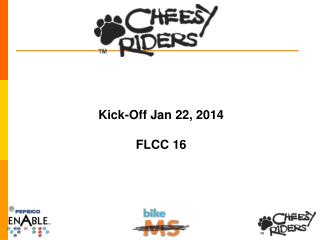
SMIC’s Fab 4 (Beijing, China) Photo by L.R. Huang, DigiTimes Better Performance/Cost Investment International Technology Roadmap for Semiconductors Market Growth PITCH IC Technology Advancement Improvements in IC performance and cost have been enabled by the steady miniaturization of the transistor Transistor Scaling Device
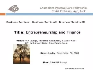
GATE LENGTH, Lg OXIDE THICKNESS, Tox M. Bohr, Intel Developer Forum, September 2004 JUNCTION DEPTH, Xj VT CURRENT |GATE VOLTAGE| The Bulk-Si MOSFET • Current flowing between the SOURCE and DRAIN is controlled by the voltage on the GATE electrode Metal-Oxide-Semiconductor Field-Effect Transistor: Gate Desired characteristics: • High ON current • Low OFF current Source Drain Substrate • “N-channel” & “P-channel” MOSFETs operate in a complementary manner “CMOS” = Complementary MOS Device
VT Roll-Off M. Okuno et al., 2005 IEDM p. 52 • |VT| decreases with Lg • Effect is exacerbated by high values of |VDS| • Qualitative explanation: • The source & drain p-n junctions assist in depleting the Si underneath the gate. The smaller the Lg, the greater the percentage of charge balanced by the S/D p-n junctions: D Large Lg: S S D Small Lg: Device
ION, low VT IOFF, low VT S VDD Sub-Threshold Leakage • Leakage current varies exponentially with VT • S ≥ 60mV/dec at room temperature, due to thermal distribution of carriers within energy bands • typically 80-100 mV/dec for a bulk-Si MOSFET log ID ION, high VT IOFF, high VT VG 0 Device
smaller Lgate Parametric Yield • High-performance processors are speed-binned • Faster chips = more $$$ (These parts have smaller Lg) • Leakage is exponentially dependent on VT = f(Lg) TOO LEAKY TOO SLOW • Since leakage is now appreciable, parametric yield is being “squeezed” on both sides Tighter control of Lg will be needed with scaling! Device
The Sub-Wavelength Gap Device
Achieving Sub-Wavelength Resolution courtesy M. Rieger (Synopsys, Inc.) Device
A geometrically regular layout should be used to improve the fidelity of printed sub-wavelength features. All MOSFETs are oriented along the same direction Gate lines are placed at regular spacings Geometrical Regularity for Improved Yield Configurable logic block layout L. Pillegi et al., 2003 DAC p. 782 Device
<l Mask Cost Considerations Mask cost escalates with technology advancement! (minimum half-pitch) It will eventually be more cost effective to use multiple lower-cost masks to define the most critical layer (gate) Device
Outline • Introduction • Spacer Lithography • Process flow • Application to gate patterning • Device Simulation Study • Summary and Future Work Device
2. Deposit mask layer (e.g. Si3N4) 1. Deposit & pattern sacrificial layer a-Si a-Si hard mask (SiO2) poly-Si gate layer gate dielectric Si 3. Anisotropically etch mask layer 4. Remove sacrificial material; Etch hardmask and poly-Si spacers a-Si Lg,min gates hard mask (SiO2) poly-Si gate layer gate dielectric gate dielectric Si Si Spacer Lithography Process hard mask (SiO2) poly-Si gate layer gate dielectric Si Note that pitch is 2 that of patterned layer! Device
Photo-lithographically defined sacrificial structures 3rd Spacers 1st Spacers 2nd Spacers High-Density Feature Formation 2n lines after n iterations of spacer lithography! Device
Spacer vs. Resist Lithography • Spacer lithography yields superior CD uniformity Y.-K. Choi et al., IEEE Trans. Electron Devices, Vol. 49, p. 436, 2002 Device
Gate Patterning using Spacer Lithography • Define fine-line features in a hard-mask layer using spacer lithography • regular geometry (lines and spaces) • Lg < l ; pitch P≤ l • Pattern fine-line features (to remove hard-mask where gate lines are not desired) • minimum feature size > P • alignment tolerance = P Lg • Define large features in a resist layer using photolithography • minimum feature size P • alignment tolerance >Lg Device
Spacer Gate Patterning Benefits • Provides fine-line gate electrodes oriented in parallel and laid out on a regular grid • Minimizes feature variations for improved yield • Facilitates RET to achieve smallest possible feature sizes tight control of Lg high parametric yield • Note that the geometrically regular mask (Step 1) can be used for multiple chip designs, to save cost Device
Achieving Uniform Gate Length Gate formation by spacer lithography uniform Lg Lg Fin formation by conventional lithography non-uniform Lg Lg Y.-K. Choi et al., IEDM Technical Digest, pp. 259-262, 2002 Device
Outline • Introduction • Spacer Lithography • Device Simulation Study • Approach • Initial results • Summary and Future Work Device
Approach • Use 3-D device simulations (Sentaurus Device) to investigate the benefits of spacer gate lithography • nominal Lg < 40nm • Sources of variation include: • Lg variations • line-edge roughness (LER) • statistical dopant fluctuations (SDF) Device
EUV Resist LER Data from AMD Average CD = 37.9nm Standard Deviation = 1.7nm Device
Impact of S/D Implant Anneal Conditions Spike: 1100°C 1s Flash: 1300°C 1ms RTA: 1000°C 10s S/D ext. implant: 3E14 As+ cm-2 @ 3keV Trend toward diffusion-less anneal increased junction roughness Device
Device Simulation: Methodology LER Generation Structure Generation Device Simulation Lg = 37nm Xj = 20.4nm Tox = 1.2nm Nbody = 2.2E18cm-3 Assume S/D junction follows LER profile. Sentaurus 3D Device simulation Collect statistical distributions of ION and IOFF Wchannel = 50nm Device
Simulated MOSFET Structures Resist Lithography Spacer Lithography Plan View (gate electrode) Isometric View Plan View (gate electrode) Isometric View Device
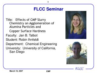
Initial Results Smaller spread in IOFFvs. ION is seen for spacer gate lithography Device
Outline • Introduction • Spacer Lithography • Device Simulation Study • Summary and Future Work Device
Summary • Tighter control of Lg will be needed with transistor scaling; however, this becomes more difficult as the “sub-wavelength gap” increases • Spacer lithography provides for better CD control, and will eventually be a more cost-effective approach than conventional resist lithography for patterning gate electrodes • LER effects on MOSFET performance can be mitigated by spacer gate lithography Future Work • Assess the relative impacts of various sources of variability (line-width variations, LER, SDF) Device