Download

1 / 28
280 likes | 444 Views
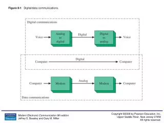
Digital Data Communications Techniques. Updated: 2/9/2009. Asynchronous and Synchronous Transmission. Timing problems require a mechanism to synchronize the transmitter and receiver receiver samples stream at bit intervals

E N D
Digital Data Communications Techniques Updated: 2/9/2009
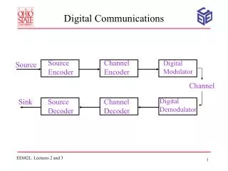
Asynchronous and Synchronous Transmission • Timing problems require a mechanism to synchronize the transmitter and receiver • receiver samples stream at bit intervals • if clocks not aligned and drifting will sample at wrong time after sufficient bits are sent • Two solutions to synchronizing clocks • asynchronous transmission • synchronous transmission
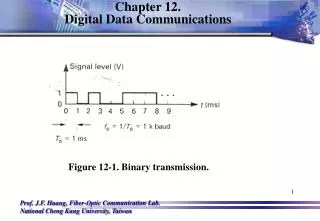
Timing Problems • Assume transmitting at 1Mbs10^-6 second per bit (1 usec) • If the clock is off by 1 percent: • After 50 cycles off by 0.5 usec • Missing one bit! Figure! 100010 rising edge How can we achieve the desired Synchronization?
Example of Timing Error • Assume data rate 10Kpbs • Bit period – 0.1 msec or 100 usec • Receiver is fast by 6% bit period is 94usec.
Asynchronous Transmission- Implementation • The frame is often made up of • Start bit • Stop elements • Parity bit • 5-8 data bits
Asynchronous - Behavior • simple • cheap • overhead of 2 or 3 bits per char (~20%) • Overhead ratio (%) = Overhead bits/Total number of bits x 100 • good for data with large gaps (keyboard) Longer blocks can generate less overhead ratio but results in more accumulative timing error!
Synchronous Transmission • block of data transmitted sent as a frame • clocks must be synchronized • can use separate clock line – over distance timing error may still occur • or embed clock signal in data • need to indicate start and end of block • use preamble and postamble • more efficient (lower overhead) than async
Synchronous Transmission • Assume Synchronous transmission • Overhead = 48 bits for every 1000 bytes (characters) of data • Calculate the overhead ratio in percentage: 48/(48+1000x8) 0.6 %
Types of Error • An error occurs when a bit is altered between transmission and reception • Single bit errors • only one bit altered • caused by white noise • Burst errors • contiguous sequence of B bits in which first last and any number of intermediate bits in error • caused by impulse noise or by fading in wireless • effect greater at higher data rates Higher data rate more errors If Data rate is 10 Mbps and the signal is lost for only 1usec, how many bit errors occur? 1usec / 0.1 usec = 10 bits!
Bit Error Rate (BER) With no error detection mechanism F is the frame size
Example • Assume bit rate is 64Kbps • There are 1000 bits per frame • Assume BER is 10^-6 • Calculate the Frame Error Rate (in one day how many errors) • If we get one frame error per day, calculate the frame error rate • Which is larger?
Error Correction • correction of detected errors usually requires data block to be retransmitted • not appropriate for wireless applications • bit error rate is high causing lots of retransmissions • when propagation delay long (satellite) compared with frame transmission time, resulting in retransmission of frame in error plus many subsequent frames • instead need to correct errors on basis of bits received
Error Correction Basic Idea • Adds redundancy to transmitted message • Can deduce original despite some errors • Errors are detected using error-detecting code • Error-detecting code added by transmitter • Error-detecting code are recalculated and checked by receiver • map k bit input onto an n bit codeword • each distinctly different • if get error assume codeword sent was closest to that received
Error Detection – Parity Check • Basic idea • Errors are detected using error-detecting code • Error-detecting code added by transmitter • error-detecting code are recalculated and checked by receiver • Parity bit • Odd (odd parity) • If it had an even number of ones, the parity bit is set to a one, otherwise it is set to a zero (P=0 if odd ones) always odd number of ones in the frame • Asynchronous applications and Standard in PC memory • Even (even parity) • Synchronous applications F(1110001) odd parity 1111 000 1 Parity Bit + Data Block
Cyclic Redundancy Check • one of most common and powerful checks • for block of k bits transmitter generates an n bit frame check sequence (FCS)
transmits n bits which is exactly divisible by some number (predetermined divisor) receiver divides frame by that number n-k bit k + (n-k) bits n-k+1 bit n-k bit CRC generator and checker Refer to your notes for examples!
Error Detection & Correction Common Techniques • Example : Division in CRC Encoder
Error Detection & Correction Common Techniques • Example : Division in CRC Decoder
http://www.macs.hw.ac.uk/~pjbk/nets/crc/ Example Message: 1010001101 Pattern: 110101 T 1010001101 + 01110 Step through to calculate the remainder!
n-k bit k + (n-k) bits n-k+1 bit n-k bit Example 1010001101 + 01110 1010001101 110101 110101 1010001101 + 01110 00000 01110
Block Code – Error Detection and Correction Table1 • Hamming Distance • The Hamming distance between two words is the number of differences between corresponding bits. • Easily found by applying the XOR operation on the two words and count the number of 1s in the result. • Ex : Hamming distance d (000,011) = 2 • Ex : Hamming distance d (10101, 11110) = 3 • Minimum Hamming Distance • The minimum Hamming distance is the smallest Hamming distance between all possible pairs in a set of words • Ex : Find the minimum Hamming distance of the coding scheme in table 1 Sol: = 2
Block Code – Error Detection and Correction • Minimum Hamming Distance • Ex : Find the minimum Hamming distance of the coding scheme in the table. • 3 parameters to define the coding scheme • Codeword size n • Dataword size k • The minimum Hamming distance dmin • We can call this (Table 2) coding scheme C(5,2) with dmin =3 • Note : the coding scheme for (Table 1) is C(3,2) with dmin =2 Table2
Relation between Hamming Distance and Error When a codeword is corrupted during transmission, the Hamming distance between the sent and received codewords is the number of bits affected by the error Ex : if the codeword 00000 is sent and 01101 is received, 3 bits are in error and the Hamming distance between the two is d (00000, 01101) = 3 To guarantee the detection of up to t errors in all cases, the minimum Hamming distance in a block code must be dmin = t + 1 t = dmin -1 To guarantee the maximum tcorrectable errors in all cases Error Detection and Correction
Error Detection and Correction • Example: Give the above coding scheme we experience 1000 bit errors when transmitting 1Gigbit bits • Calculate the bit error rate. • Calculate the ratio of data to coding rate. • Using the given encoding technique, what is the codeword for 11? • What is the coding scheme: C(n,k),What is dmin? • How many errors can be detected using the given encoding technique? • How many errors can be corrected using the given encoding technique? • Calculate the code gain. • Assume the received codeword is 00101. What will be the likely original dataword? Rotate to left: 11110 t = dmin -1=3-1=2 t = 1
Error Detection and Correction • The larger the dmin the better • The code should be relatively easy to encode/decode • We like n-k to be small reduce bandwidth • We like n-k to be large reduce error rate
Channel bit error rate 10^-6 System Performance • Assume n=4, k=2 • Given BER, coding can improve Eb/No • Lower Eb/No is required) • Code gain is the reduction in dB in Eb/No for a given BER • E.g., for BER=1-^-6 code gain is 2.77 dB • Energy per coded bit (Eb) = ½ data bit (Ed) • If BET – 10^-6 required energy is 11 dB • Hence, bit error rate will be 3dB les • This is because Ebit=2xEdata • For very high BER, adding coding requires higher Eb/No due to overhead