Download
1 / 23
240 likes | 287 Views
Elevator Control Unit. Elevator Control Unit (ECU).

E N D
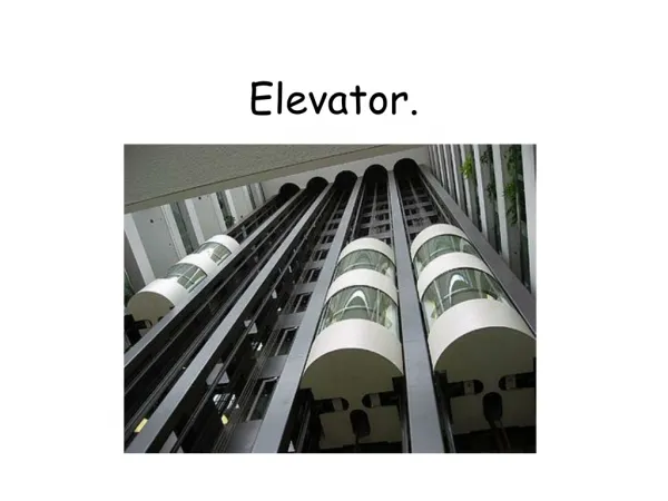
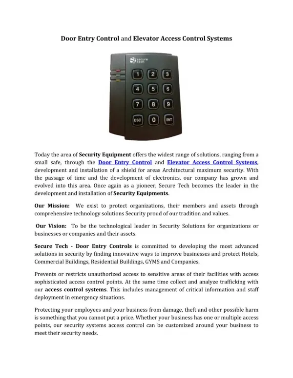
Elevator Control Unit (ECU) • The Elevator Controller Unit is used to interface the Millenium Windows System to an elevator controller. Each ECU is capable of controlling up to 16 floors and a total of 4 ECU’s can be connected to a single SCU, for a total of 64 floors of control. • This device is typically located inside the elevator control room and a qualified elevator technician is required to wire it.
ECU Spec’s • Input: • 120 VAC, 60 Hz, 2amps unswitched circuit. (P/N EC2-101190) • 240 VAC, 50 Hz, 2amps unswitched circuit. (P/N EC2-101191) • Fuse: • AC Input,1/2 amp, slow blow. • Data Storage: • 24 hr minimum clock and memory backup • Alarm Inputs: • 4 non-supervised alarm inputs • Outputs: • 16 Form “C” relays. Contacts rated for 5 amps @ a nominal 24 VDC. All relays are energized.
ECU Tech Notes • The ECU and the associated wiring should be installed by a licensed elevator technician. • The ECU’s should be on a common dedicated circuit breaker. • Keep all low voltage wiring away from elevator conduits and power transformers. • Make sure the ECU addressing is correct. The first ECU must be programmed as address “0”. • Use a dedicated SCU and Power Supply for connecting to ECU’s. No other devices such as DCD’s, and RCD’s should be connected to this SCU.
ECU Tech Notes • The inbound data trunk cable and the power cable should have some form of identification like a piece of electrical tape around the jacket to ensure that future trouble shooters know which direction the power and data source is feeding from. • The inbound and outbound shield of the trunk data cable, along with the ECD shield should be twisted together and fastened with an electrical crimp or wire nut. The shield should not connect to any terminals of the ECU PCB. • ECU’s do not have battery backup. If power is lost, then the card reader portion of the elevator will stop working.
ECU Tech Notes • The cable shielding for the data trunk connections should use the “Monolithic Grounding” method. • A Manual Override Keyswitch must be employed to satisfy the Fire Department requirements to shut down the access control functions on an elevator during a fire. • ECU’s are sold with an enclosure.