Download
1 / 22
240 likes | 458 Views
Rapid Prototyping. Tarek a. tutunji. Prototype. A prototype can be defined as a model that represents a product or system. This model is usually used for functionality testing and product visualization.

E N D
Rapid Prototyping Tarek a. tutunji
Prototype A prototype can be defined as a model that represents a product or system. This model is usually used for functionality testing and product visualization. Prototyping is essential in the development of products and all industrial nations have prototyping centers. In fact, prototyping plays a major role in the advancement of technology.
Prototype • In the prototyping development cycle, initial prototypes are built, tested, and then reworked as necessary until an acceptable prototype is finally achieved from which the complete system or product can be developed. • Three types of prototyping • PCB Prototyping • Virtual Prototyping • Rapid Prototyping
PCB Prototyping The production of a functional Printed Circuit Board (PCB). The product can then be tested for its functionality and reliability
Virtual Prototyping Computer-based without the option of a physical part or object. It uses virtual reality to create product prototypes and test their properties. It provides a virtual 3-D prototype that can be manipulated from all views and angles. The computer program can then test many aspects of the product such as vibration, forces, materials and weight.
Rapid Prototyping Produces physical prototypes in short time (within hours or days rather than weeks). These prototypes are frequently used to quickly test the product's look, dimension, and feel. Rapid prototyping usually can result in plastic objects.
Prototyping Advantages • Provides the proof of concept • Shows the users how the final system would look like • Reduces development costs • Increases system development speed and quality • Assists to identify any problems with early designs • Refines the potential risks associated with the product delivery
Rapid Prototyping Most of the material in the following slides are from the reference: John Wiley & Sons, Inc. M P Groover, Fundamentals of Modern Manufacturing3/e
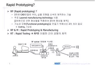
Rapid Prototyping (RP) • A family of fabrication processes developed to make engineering prototypes in minimum lead time based on a CAD model of the item • Traditional method is machining • Can require significant lead-times – several weeks, depending on part complexity and difficulty in ordering materials • RP allows a part to be made in hours or days, given that a computer model of the part has been generated on a CAD system
Why is Rapid Prototyping Important? • Product designers want to have a physical model of a new part or product design rather than just a computer model or line drawing • Creating a prototype is an integral step in design • A virtual prototype (a CAD model of the part) may not be sufficient for the designer to visualize the part adequately • Using RP to make the prototype, the designer can see and feel the part and assess its merits and shortcomings
RP – Two Basic Categories: • Material removal RP - machining, using a dedicated CNC machine that is available to the design department on short notice • Starting material is often wax • Easy to machine • Can be melted and resolidified • The CNC machines are often small - called desktop machining • Material addition RP - adds layers of material one at a time to build the solid part from bottom to top
CAD / CAM • Computer-Aided Design (CAD) • A designer starts with an idea of a new product and uses the CAD software to create a preliminary design. • The preliminary design can also be analyzed for functionality as the design is being created. • Modifications and reanalyzes of the computer model can be done • Computer-Aided manufacturing (CAM) • Used to drive appropriate machinery to physically create the part. • The entire design cycle is shortened • Engineers can go from design to prototype in a matter of days, instead of weeks or months
Steps to Prepare Control Instructions for RP Geometric modeling - model the component on a CAD system to define its enclosed volume Tessellation of the geometric model - the CAD model is converted into a computerized format that approximates its surfaces by facets (triangles or polygons) Slicing of the model into layers - computerized model is sliced into closely-spaced parallel horizontal layers
Solid Model to Layers Conversion of a solid model of an object into layers (only one layer is shown).
RP Technologies • There are several RP technologies. The most common three are: • Stereolithography • Laminated Object Manufacturing • 3-D Printing
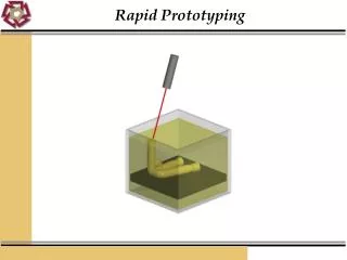
Stereolithography (STL) Starting material is liquid RP process for fabricating a solid plastic part out of a photosensitive liquid polymer using a directed laser beam to solidify the polymer Part fabrication is accomplished as a series of layers - each layer is added onto the previous layer to gradually build the 3-D geometry
Stereolithography Stereolithography: (1) at the start of the process, in which the initial layer is added to the platform; and (2) after several layers have been added so that the part geometry gradually takes form.
Laminated Object Manufacturing (LOM) Starting material is solid Solid physical model made by stacking layers of sheet stock, each an outline of the cross-sectional shape of a CAD model that is sliced into layers Starting sheet stock includes paper, plastic, metals, or fiber-reinforced materials The sheet is usually supplied with adhesive backing as rolls that are spooled between two reels After cutting, excess material in the layer remains in place to support the part during building
Laminated Object Manufacturing Laminated object manufacturing.
Three Dimensional Printing (3DP) Starting material is powder Part is built layer-by-layer using an ink-jet printer to eject adhesive bonding material onto successive layers of powders Binder is deposited in areas corresponding to the cross sections of part, as determined by slicing the CAD geometric model into layers The binder holds the powders together to form the solid part, while the unbonded powders remain loose to be removed later
Three Dimensional Printing Three dimensional printing: (1) powder layer is deposited, (2) ink-jet printing of areas that will become the part, and (3) piston is lowered for next layer (key: v = motion).