Download
1 / 49
490 likes | 509 Views
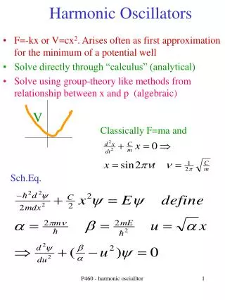
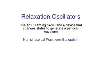
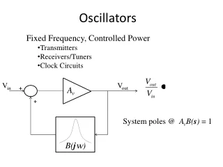
Oscillators. Need of an Oscillator. An oscillator circuit is capable of producing ac voltage of desired frequency and waveshape. To test performance of electronic circuits, it is called signal generator. It can produce square, pulse, triangular, or sawtooth waveshape.

E N D
Need of an Oscillator • An oscillator circuit is capable of producing ac voltage of desired frequency and waveshape. • To test performance of electronic circuits, it is called signal generator. • It can produce square, pulse, triangular, or sawtooth waveshape. • High frequency oscillator are used in broadcasting. • Microwave oven uses an oscillator. • Used for induction heating and dielectric heating.
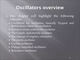
Types of Oscillators • Sinusoidal or non-sinusoidal. • An oscillator generating square wave or a pulse train is called multivibrator : • Bistable multivibrator (Flip-Flop Circuit). • Monostable multivibrator. • Astable multivibrator (Free-running). • Depending upon type of feedback, we have • Tuned Circuit (LC) oscillators. • RC oscillators, and • Crystal oscillators.
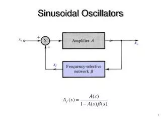
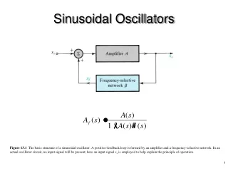
Using Positive Feedback • The gain with positive feedback is given as • By making 1 – Aβ = 0, or Aβ = 1, we get gain as infinity. • This condition (Aβ = 1) is known as Barkhausen Criterion of oscillations. • It means you get output without any input !
How is it Possible ? Connecting point x to y, feedback voltage drives the amplifier.
What happens to the output ? • There are three possibilities.
(3) If Aβ = 1, we get sustained oscillations. In this case, the circuit supplies its own input signal.
Wherefrom comes the starting voltage ? • Each resistor is a noise generator. • The feedback network is a resonant circuit giving maximum feedback voltage at frequency f0, providing phase shift of 0° only at this frequency. • The initial loop gain Aβ > 1. • The oscillations build up only at this frequency. • After the desired output is reached, Aβ reduces to unity.
Tank Circuit • LC parallel circuit is called tank circuit. • Once excited, it oscillates at
The energy keeps oscillating between electric potential energy and magnetic filed energy.
Hartley Oscillator • Note that in the collector-tuned circuit, two inductor coils are used. • One end of these coils is grounded. • If we make the tickler coil an integral part of the circuit, we get Hartley Oscillator.
When the tank circuit resonates, the circulating current flows through L1 in series with L2. Hence the equivalent inductance is The feedback factor is
Colpitts Oscillator • An excellent circuit. • Widely used in commercial signal generators. • Uses two capacitors instead of the inductive voltage divider.
RC Oscillators • Two types : • RC Phase shift Oscillator. • Wein Bridge Oscillator.
A phase-lead or phases-lag circuit can provide phase shift between 0° and 90°. • For total phase shift 180°, we use three identical sections each giving a phase shift of 60°. & • It means in the beginning the gain of the FET amplifier must be greater than 29. • Not very popular, as the frequency cannot be adjusted over large range.
The two arms on the left of the bridge make lead-lag circuit. • The two arms on the right, are 2Rt and Rt, making a potential divider. • It has both positive and negative feedback paths. • Initially, when switched on, there is more positive feedback than negative feedback. • Oscillations build up. • Negative feedback increases, making Aβ = 1.
The reason why the loop gain reduces to unity : • Initially tungsten lamp has low resistance; giving low negative feedback. • Thus, loop gain Aβis greater than unity. • As oscillations are built up, the tungsten lamp heats up increasing its resistance. • Negative feedback increase to make Aβ = 1. • With sustained oscillations, the resistance of the lamp increases to exactly Rt , so that the gain becomes :
At resonance, the voltage ratio or feedback factor of the lead-lag circuit is 1/3. • Therefore, loop gain becomes unity. • The oscillation frequency is the same as that of the lead-lag circuit,
Crystal Oscillator • Used when accuracy and stability of fo is utmost important. • Where do you need such high stability of frequency of oscillations ? • Instead of an inductor, it uses a crystal of quartz, tourmaline, or Rochelle salt. • Piezoelectric effect. • The crystal is suitably cut and then mounted between two metallic plates. • The fundamental frequency is given as
Cm (mounting capacitance) = 3.5 pF; Cs = 0.0235 pF; L = 137 H; R = 15 kΩ
Crystals have incredibly high Q. • For the given values, Q = 5500. • Q as high as 100 000 can be possible. • An LC circuit has Q not greater than 100. • The extremely high value of Q makes fo highly stable.
Series and Parallel Resonance • First, resonance occurs at fs for the series combination of L and Cs. • Above fs the series branch LCsR has inductive reactance. • It then resonates at fp , with Cm. • For this parallel resonance, equivalent series capacitance is Cp.
Normally, Csis much smaller than Cm. • Therefore, Cp is slightly less than Cs. • Hence, the frequency fp is slightly greater than fs. • The crystal is inductive only between the frequencies fs and fp. • The frequency of oscillation must lie between these frequencies. • Hence the stability.
Review • Need of an Oscillator. • Types of Oscillators . • Using Positive Feedback. • Barkhausen Criterion of Oscillations. • Starting Voltage . • Tank Circuit. • Tuned Collector Oscillator. • Tuned-Drain Oscillator. • Hartley Oscillator. • Colpitts Oscillator. • RC Phase Shift Oscillator. • Wien Bridge Oscillator. • Crystal Oscillator. • Series and Parallel Resonance