Download
1 / 25
250 likes | 436 Views
Properties of Instrumentation. Nuclear Engineering 304. Objectives. Learn how to use an oscilloscope Significance of different modes of operation of oscilloscope Measure the gain of an amplifier with an oscilloscope Observe the output pulses from a Linear amplifier

E N D
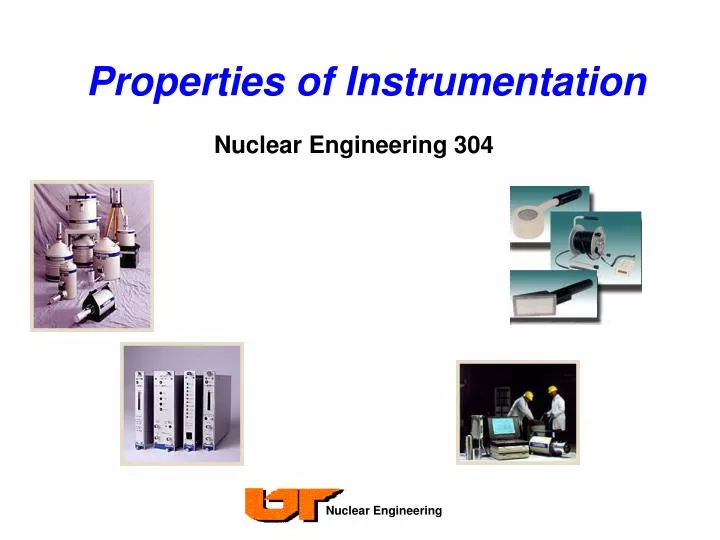
Properties of Instrumentation Nuclear Engineering 304
Objectives • Learn how to use an oscilloscope • Significance of different modes of operation of oscilloscope • Measure the gain of an amplifier with an oscilloscope • Observe the output pulses from a • Linear amplifier • Single channel analyzer (SCA) [discriminator] • Detector • Operate the counters with the window of the SCA at several positions
Objectives (cont) • Obtain a 60Co energy spectrum with the multichannel analyzer (MCA) • Operate the MCA in pulse height and time modes • Understand the function and operation of each component used in this experiment • Understand the limitations of each component and the interactions between various components • Become competent in the operation of selected counting equipment so that future experiments can be conducted in a timely manner
Precautions • Be careful with charge sensitive preamplifiers. Turn off the voltage before disconnecting. This preamplifier is easy to damage and expensive to repair. • Verify that the input voltage to a particular device is within specifications. • Use an oscilloscope to review your output signals from each NIM device. • Improper termination and mismatched impedances (either 50 or 1M ) will cause signal echoes – known as ringing – which lead to false counts.
Oscilloscope Scaler and timer Multichannel analyzer (MCA) Single channel analyzer (discriminator) Precision pulser Scintillation detector Photomultiplier tube Preamplifier Linear amplifier Cables and connectors Equipment
Oscilloscopes • Oscilloscope is analogous to a camera that captures signal images that we can measure and interpret • Is it an accurate picture of what actually happened? • Is the picture clear or fuzzy? • How many pictures can we take per second? • Characteristics of oscilloscopes • Number of channels • Bandwidth • Digital vs. Analog • Sample rate • Rise time
Characteristics of Oscilloscopes • Most scopes have either 2 or 4 channels (inputs) • Can use 2nd channel as trigger for 1st channel • View one or more waveforms at once • Bandwidth • Typical range 100 – 400 MHz affordable scopes (~ 50 GHz max) • Determines fundamental ability to measure a signal and resolve high-frequency changes • Note that limiting the bandwidth reduces noise and provides a cleaner signal
Characteristics of Oscilloscopes • Sample rate • How frequently a digital oscilloscope takes a snapshot or sample of the signal.
Oscilloscope Fundamentals • Front panel of scope divided into four main sections • Vertical (volts/div) • Horizontal (sec/div) • Trigger • Display • Three basic adjustments • Attenuation or amplification of the signal. Use the volts/div control to adjust the amplitude of the signal • Time base. Use the sec/div control to set the amount of time per division. • Use the trigger level to stabilize a repeating signal, or to trigger on a single event.
Oscilloscope Fundamentals • Vertical System Controls • Termination (1M or 50 ohm) • Position • Allows you to move waveform up and down on screen • Volts/Division • Scale factor. The maximum voltage you can display on the screen is the volts/div setting multiplied by the number of vertical divisions. • Coupling (AC, DC, Ground) • DC coupling shows all of an input signal • AC coupling blocks the DC component of a signal so waveform is centered around zero • Ground disconnects the input signal from the vertical, which lets you see where zero volts is located on the screen. Switching from DC to ground is a handy way of measuring signal voltage with respect to ground.
Oscilloscope Fundamentals AC and DC Input Coupling
Oscilloscope Fundamentals • Horizontal System Controls • Trigger Position • Allows you to move waveform left and right on screen • Seconds/Division • Scale factor. Selects the rate at which the waveform is drawn across the screen • XY mode lets you display an input signal, rather than the time base, on the horizontal axis • This mode of operation allows for phase shift measurement techniques
Oscilloscope Fundamentals • Trigger Controls • Crucial for clear signal characterization because it synchronizes the horizontal sweep at the correct point of the signal, thus • Trigger Sources • Any input channel • The power source signal • An external source other than the signal applied to an input channel • A signal internally defined by the oscilloscope, from one or more input channels allowing you to stabilize repetitive waveforms.
Oscilloscope Fundamentals • Trigger Modes • In normal mode the oscilloscope only sweeps if the input signal reaches the set trigger point; otherwise (on an analog oscilloscope) the screen is blank or (on a digital oscilloscope) frozen on the last acquired waveform. Can be disorienting since you may not see the signal at first if the level control is not adjusted correctly. • In auto mode the oscilloscope will sweep, even without a trigger. If no signal is present, a timer in the oscilloscope triggers the sweep. Ensures that the display will not disappear if the signal does not cause a trigger.
Oscilloscope Fundamentals • Trigger Level and Slope • The slope control determines whether the trigger point is on the rising or the falling edge of a signal. A rising edge is a positive slope and a falling edge is a negative slope • The level control determines where on the edge the trigger point occurs
Nuclear Instrumentation • Scaler / Timers • Adjustable timer used to determine count window • selectable resolution of 0.01 seconds or 0.01 minutes • 3 levels of multipliers (NM * 10P) • Scaler is the basic NIM counting system • Usually at least 100 Mhz (100 million counts per sec) • Accept negative or positive pulses (jumper selectable) • Pulse pair resolution ~ 10 ns • Min. pulse width to be counted ~ 4 ns • Input range ~ +100 mv to + 10V • Must “filter” input using SCA to prevent low levelnoise from appearing to be actual counts
Nuclear Instrumentation • Single Channel Analyzer (Discriminator) • Prepares amplifier output pulse for input into counting devices • Without discrimination, system noise causes false counts • Gives standardized (+) output or logic signals (fast or slow) • Improper settings results in lost counts or measuring noise • Discrimination of pulses above and below a certain amplitude • Only pulses corresponding to a energy window are passed • Lower threshold set at E, upper threshold at ∆E All voltage pulses between the given energy range are counted
Nuclear Instrumentation • Linear Amplifier • Amplification is minor role, pulse shaping is true purpose • Complex active filters, Gaussian • Convert preamplifier output into suitable signal • Generally used for semiconductor detectors,proportional counters, and scintillation detectors • Usually do not use Linear Amp and SCA in samesignal path • Major features • Coarse gain, fine gain, selectable input polarity • Selectable pulse shaping time (cutoff frequency) • Front panel BNC inputs or rear pre-amp inputs
Nuclear Instrumentation • Precision Pulser • Simulates output from scintillation detector/preamplifier • Method to test and calibrate counting system • Major features • Repetition rates up to 2 kHz • Selectable square or tail pulse • Three decay constants for tail pulse • Selectable pulse height 0 to +10V (0 to +5V at 50 termination) • SYNC provides trigger signal pulse for oscilloscope • Attenuators to change between various signal levels
Detectors, PMT’s & PreAmps • The general types of detectors • Gas-filled detectors (ion chambers, GM, proportional detectors) • Semiconductor detectors (HPGe, CdTe, Si) • Scintillation detectors (NaI, fast plastics) • Good timing and poor energy resolution (fast plastics) • Good energy resolution (NaI) – but not as good as semiconductors • has no mass or charge, it cannot be detected directly • interaction produces cascade of secondary charged particles • Photoelectric effect • Compton scattering • Pair Production • Electrons interactions produce pulses of light (fluoresce) • Fluorescence converted to electrical pulse by PMT
Detectors, PMT’s & PreAmps • Photomultiplier tube converts extremely weak light output from crystal into electrical signal • Only a few hundred light pulses in typical interaction • PMT amplification creates 107 – 1010 electrons per pulse • Have fairly linear response, and maintain most of the timing information of original event
Detectors, PMT’s & PreAmps • Three essential functions • Conversion of charge to voltage pulse • Signal amplification • Pulse shaping • Place close to detector to minimize noise & transmission losses in cables • Output pulse with an amplitude proportional to the integrated charge from the detector • Input from the anode signal • Positive polarity pulse output • May have separate anode and dynode outputs • Used with HPGe, NaI, plastics scintillatorsand proportional detectors
Radioactive Sources • Co-60 sources • 60Co 60Ni* + β- + anti- [0.3179 MeV total for beta & antineutrino]60Ni* 1.17 MeV + 1.13 MeV • T1/2 = 5.27 years • Don’t assume 3 months time doesn’t make difference in activity, ~ 4% • Always express in mCi or some equivalent • 1 dps = 1 Bq • 1 mCi = 3.7 E 10 dps = 2.22 E 12 dpm • 1 measured count ≠ 1 source disintegration due to detector efficiencies • Need efficiencies or coincidence counting techniques to determine measured activity
MultiChannel Analyzer (MCA) • Two primary modes • PHA = Pulse Height Analysis (Counts vs. Energy) • MCS = Multichannel Scaling (Counts vs. Time) • In PHA mode can be thought of as a series of SCA’s • Collects pulses in all voltage ranges at once • Have height or amplitude proportional to energy • Count the number of occurrences at each energy and form histogram • Displays information in real time • In MCS modes can be though of a a series of scalers • Each channel corresponds to a time “bin” • Step through channels based on internal clock or external pulse (trigger) • Applications include half-life measurements
References • Tektronix • www.tektronix.com • Canberra • www.canberra.com • Ortec • www.ortec-online.com • Ludlum Instruments • www.ludlums.com