Download
1 / 9
100 likes | 285 Views
Relationship between V & I. If the temperature is kept constant, we can study the relationship between V & I. We use the following circuit to study this relationship:. Relationship I, V & R.

E N D
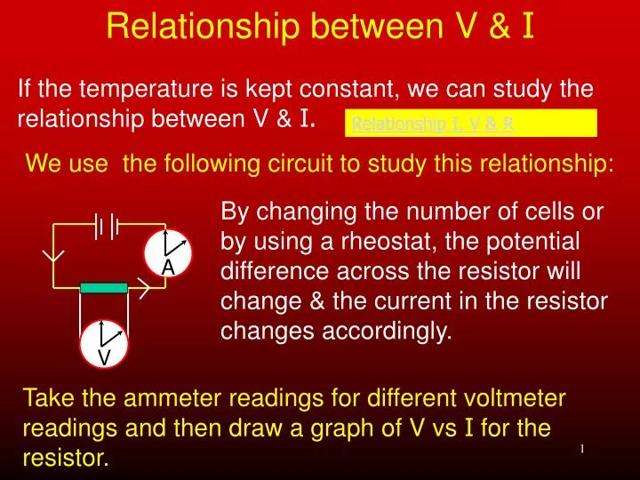
Relationship between V & I If the temperature is kept constant, we can study the relationship between V & I. We use the following circuit to study this relationship: Relationship I, V & R By changing the number of cells or by using a rheostat, the potential difference across the resistor will change & the current in the resistor changes accordingly. A V Take the ammeter readings for different voltmeter readings and then draw a graph of V vs I for the resistor.
Relationship between V & I V in volts I in amperes 1,2 0,160 2,3 0,307 3,5 0,467 4,6 0,610 = 7,5 Ω A graph of V vs I can now be drawn for these sets of readings. From this graph we see that the gradient or slope is constant and V ∝I and the gradient gives us the resistance of the resistor 5 3 1 0 V V V I I Gradient = = R 0 0,1 0,3 0,5 I
Ohm’s Law Ohm's law Since V ∝I at constant temperature, we can see that the resistance is thus staying constant. From this we can state Ohm’s Law: The current in a metallic conductor is directly proportional to the potential difference across its ends, provided the temperature remains constant. The unit of resistance is the V.m-1 also called the ohm (Ω). A conductor has a resistance of 1Ω if the current in it is 1A when the potential difference across the ends is 1V. Ohm's law Ohm's law Click here
Equations for finding I Vemf V resistor I = I = Rresistor Rtot The following equations may be used to find the current in a circuit: R = V/I Be careful not to ‘mix & match’ these variables
Special concepts about circuits Resistors in series: Current same at all points V for whole circuit = sum of V across each resistor Vtot = V1 + V2 + V3 Same V acrossidentical resistors Unequal resistors split Vtot unequally – with higher resistance having the higher V. Circuit Construction Kit (DC Only) - Electricity, Circuits, Current - PhET
Special concepts about circuits I x R i1 = r Resistors in parallel: V across each is the same I = i1 + i2 + i3 Identical resistors carry same current Unequal resistors carry unequal currents with the smaller the smaller resistor carrying larger current Combinations of resistors Click here Now try as many electrical circuit problems as you can find. Current in parallel branch
Temperature & resistance V I R = The resistance of a resistor is determined by: The resistance of a conductor usually remains constant – unless it becomes hot – when its resistance increases. However, at very low temperatures – certain substances become ‘superconductors’ – where they have virtually no resistance at all. Temperature affecting resistance
Temperature & resistance: Ohmic & non-Ohmic conductors An Ohmic conductor is one that obeys Ohm’s law i.e. when the V is changed across the conductor, so the I through the conductor changes proportionally – provided the temperature remains constant. A non-Ohmic conductor does not obey Ohm’s law. Its resistance increases as the temperature of the resistance changes. Filament – non-Ohmic conductor Resistor – Ohmic conductor
Graphs for Ohmic & non-Ohmic conductors Resistance and temperature Ohmic non-Ohmic Ohmic and non-ohmic conductors