Download
1 / 23
230 likes | 415 Views
Combustion Monitoring System. Silas Harris Tsjellum van der Stok. Problem Statement. VTC has requested a device that will monitor the combustion process of the Fröling pellet boiler in the Red School House. This will be performed by measuring: CO (Carbon Monoxide), CO 2 (Carbon Dioxide)

E N D
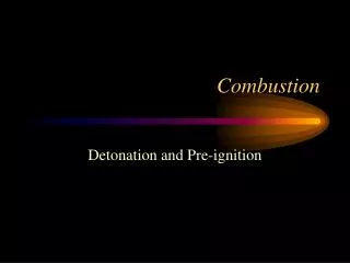
Combustion Monitoring System Silas Harris Tsjellum van der Stok
Problem Statement • VTC has requested a device that will monitor the combustion process of the Fröling pellet boiler in the Red School House. This will be performed by measuring: • CO (Carbon Monoxide), CO2 (Carbon Dioxide) • Particulate Emissions
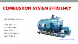
A biomass pellet boiler was installed in the Red School House to reduce heating oil use and study the use of grass and other locally grown biomass for heating fuel. One objective of the project was to outfit the facility to monitor the combustion process for efficiency and particulate emissions. This project was supported by the Department of Energy under the Sustainable Energy for Homes and Businesses program. Award number DE-EE0000386 Grant number 02240-SANDERS-003
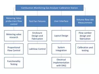
Our Solution • Design a system that will sample gas from the exhaust of the pellet boiler: • Sample to gas analyzer • 2) Sample to particulate monitoring
System Diagram Q From Fröling Exhaust ΔP Particulate Monitoring Flue Flow Flow Metering Valves Probe Train DAQ & LabVIEW Control Gas Analysis Gas Conditioning Flow Measurement Gas Analysis Gas Sampling Lines Electrical Communication
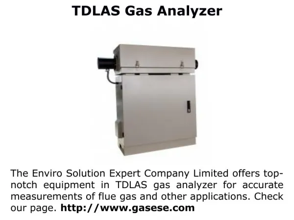
Gas Analysis Fine Control Valve Flow Meter DAQ & LabVIEW Control CAI ZRE NDIR
Gas Analysis • The gas analyzer will take samples and output the levels of CO and CO2 flowing through the system. These values are used to calculate the burn efficiency using a mass balance relationship.
DAQ & LabVEW Control Across Secondary Orifice Plate
Particulate Monitoring Gas Sample Flow Direction
Flow Rate Measurement Stack Exhaust Flow (Uninterrupted) Sample Flow (to probe train and gas analysis) Known Proportion
Flow Rate Using Flat Plate Orifice Q ΔP Sensor Q= volume flow rate (ft3/min) C0= discharge coefficient A0= cross-sectional area, normal to flow (ft2) P1= downstream pressure (lb/ft2) P2= upstream pressure (lb/ft2) ρ= density (lb/ft3) β= ratio of diameters (d to D)
Pressure Tap Placement 1/2D From Plate 1D From Plate Low Pressure High Pressure D Vena Contracta: Any point in a fluid stream emerging from an orifice where the cross sectional area of the stream is at it’s minimum. Highest Velocity, Lowest Pressure
Particulate Monitoring Train Control Logic Qrequest= Qmeasured? Increases voltage to proportional valve controller (increase Qmeasured) Qrequest= Qstack/Proportion Greater Decreases voltage to proportional valve controller (decrease Qmeasured) Lower Qstack = flow rate through the exhaust stack (CFM) Qmeasured= flow rate through the particulate train (CFM)
LabVIEW Developed by National Instruments, LabVIEW is a graphical programming language that allows seamless integration of external inputs and outputs. These programs are known as VIs, or Virtual Instruments. DAQ – Data Acquisition Unit
Next Steps • Calibration gas testing • Automatic gain control for valve controller • Integration with pellet boiler
Thank You Mark Champion at HearthLab Solutions Roger Howes Mike Wright Bob Royce John Kidder